uoficowboy
Full Member level 3

- Joined
- Apr 4, 2009
- Messages
- 169
- Helped
- 6
- Reputation
- 12
- Reaction score
- 5
- Trophy points
- 1,298
- Location
- Seattle, Wa, USA
- Activity points
- 2,964
How to analyze and optimize this circuit? (current source using FET and OA)
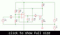
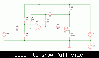
Hi - I want to modify a current source circuit. I've attached a screen capture of the circuit in LTSpice as well as the bode plot of the output (the drain of M1 - though really the output is the current through R2). The current values are mostly just values that I found that produced decent results. The FET was chosen to be wimpy and my hope was that it would have low transconductance (I thought that would help with stability). The OA was chosen to be a fairly general purpose precision OA with fairly normal GBP (1MHz).
The bode plot looks generally like a three pole low pass filter to me (but I could be missing something!) It looks like R4 + C1 gives the first pole [at 1/(2*pi*R4*C1)]. The second pole is from R3 and the Ciss of M1 [again, 1/(2*pi*R3*CissM1)]. The third from the OA.
To optimize this circuit, I'm thinking I'd want to get the first two poles to be at whatever filter function I want (ie choose them to match that of a two pole bessel). And I'd want the pole from the OA to be way past the other two (so as to keep gain high before the cutoff frequency of the first two poles). Does that all make sense? Is there any important relationship between the R4/C1 pole and the R3/M1 pole that I need to be careful of? (ie make sure one is at a lower frequency than the other, or something like that). Any general feelings on how to choose the GBP of my OA? Any other OA parameters I should be concerned about?
As for what I care about from this circuit - I want DC accuracy, stability, ability to handle the voltage on the FET source changing (there will be the equivalent of a AC voltage source between the bottom of R2 and ground in the actual circuit that this is going into) and bandwidth around maybe 1KHz (that part isn't completely nailed down yet). The circuit is for a personal project.
Thanks for your help!!
Attachments
Last edited:


