Continue to Site

Welcome to EDAboard.com

Welcome to our site! EDAboard.com is an international Electronics Discussion Forum focused on EDA software, circuits, schematics, books, theory, papers, asic, pld, 8051, DSP, Network, RF, Analog Design, PCB, Service Manuals... and a whole lot more! To participate you need to register. Registration is free. Click here to register now.

TL431 Problem in SMPS circuit

Status
Not open for further replies.

baby_1

Advanced Member level 1
Joined
Dec 3, 2010
Messages
415
Helped
1
Reputation
2
Reaction score
1
Trophy points
1,298
Visit site
Activity points
4,277
Hello
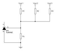
as you see this image,vout is equal :
gif.latex


but in SMPS circuit i see something interesting.
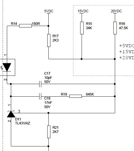
87_1338395649.jpg


Vout=2.5(1+47.5/2.7)=46.48 :shock:

another one
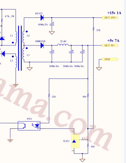
40_1338395649.jpg


Vout=2.5(1+12000/100)=302.5:shock:

if i change the R1 and R2 in this equation i have these result
Vout=2.5(1+2.7/47.5)=2.64
Vout=2.5(1+100/1200)=2.708

it means if output voltage is fix on the desire volt it has error !!!!

why?
what is my fault?

---------- Post added at 21:20 ---------- Previous post was at 21:09 ----------

Please tell me how the Tl431 work in SMPS circuit?
 

Hi
It is simple . We have a transient response for out put capacitor . hence the voltage at start time has an exponential change . thus when the TL431 conduct ( at 2.5 volts , but with a divider we can increase it simply ! ) (across it ) . the opto coupler will turn on and the CE of it's transistor will have linear behavior and thus the voltage will stabilize .
I hope you got my meaning .
Best Wishes
Goldsmith
 

Thanks Dear goldsmith
but as you see the formula it seems doesn't work properly?why?
and i test the circuit with some different resistor.how it detect the changes in output voltage because it vo of Tl431 doesn't related to the Vo... its correct that
gif.latex
but i can't how it works?it vo change the what parameters of TL431 change?and how can find the changes parameters equation?
 

It is the general way , and i have used it for many of my designs . i told you how it will detect . this loop will control the opto coupler as a linear device .
And the other thing , is : don't forget that the TL431 needs 2.5 volt at it's reference pin , to operate . it's minimum voltage will be 2.5 volts ( break voltage ) and if you use a voltage divider , you can control the out put . for example instead of 50 volt , pin 1 can be 2.5 volts and it will conduct . you understand ?
 

Vout=2.5(1+12000/100)=302.5
I think that's not possible....
you're not reading the entire data sheet! Check the specs, e.g. Vka can't exceed a certain value.
By your theory, we can generate kV with a TL431.
 

@baby_1

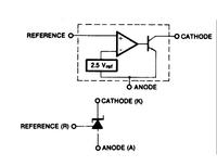
The TL431 is a shunt regulator, in other words, that’s some kind of programmable zener diode, mainly because:
- It associates an open-collector op amp and a reference voltage
- The internal circuitry is self-supplied from the cathode current
- When the control pin exceeds 2.5 V, it sinks current from its cathode
In classical loop-control configuration, the TL431 observes a fraction of the output voltage seen by its ref pin and converts it into an output current sank between the cathode and the anode. So in a SMPS the TL431 is usually placed on the isolated secondary side to feed the error back to the primary side via an optocoupler.
 
  • Like
Reactions: baby_1

    baby_1

    Points: 2
    Helpful Answer Positive Rating
This formula is only correct if there is one output voltage, connected to the reference pin with one resistor.

In both of your examples there is more than one output voltage, and all the output voltages are connected to the reference pin with resistors. In this case the calculation is more complicated.

(I read your questions properly before writing an answer. ;-))

---------- Post added at 02:40 ---------- Previous post was at 02:05 ----------

For more than one output, you can use this formula:
(Vout1 - 2.5) / R1 + (Vout2 - 2.5) / R2 + (Vout3 - 2.5) / R3 = 2.5 / Rx

 
Last edited:
  • Like
Reactions: baby_1

    baby_1

    Points: 2
    Helpful Answer Positive Rating
Hello
Thanks for all response.
dear godfreyl
if we now assume that o single input and omit the other fraction ((Vout2 - 2.5) / R2 + (Vout3 - 2.5) / R3) we have
(Vout1 - 2.5) / R1 = 2.5 / Rx

example one that R1=47.5 and Rx=2.7 , Vout1=20

(20-2.5)/47.5=.36

2.5/2.7=.92

they aren't the same.

could you tell me I realized the TL431 responsibility in SMPS circuit right?
if output voltage want to increase the output voltage of voltage divider(Resistor network) increase and if it is more than 2.5 volt the output of TL431 current try to be more and it feedback to input and cause to change PWM duty cycle to decrement.
but as you see the formula the output voltage of voltage divider network doesn't related to the output of TL431 and it shows us only depends of the value of the network resistor!!!! why?!!!!!
but if we see the input schematic(that show us the internal and transistor in it) we can use the voltage divider voltage that show us the Vo(tl431)=GainOpamp*Vout(R2/(R1+R2))
but this equation doesn't work with SMPS circuit.
what is my fault?

---------- Post added at 10:17 ---------- Previous post was at 09:39 ----------

Hello
could you give me an example and calculation? i want to have a specific output voltage with SMPS circuit 30volt output ?
 

Thanks goldsmith
could you give me an example and calculation? i want to have a specific output voltage with SMPS circuit 30volt output that want to use Tl431
 

Sure , 30=2.5*R1/R1+R2 if you select one of the resistors randomly , the other one will given . you can test it ! when vref be 2.5 volts it will conduct . i don't know what thing is unclear in this simple formula
 
  • Like
Reactions: baby_1

    baby_1

    Points: 2
    Helpful Answer Positive Rating
Thanks Dear goldsmith
1-it means we calculate the R1 and R2 with output voltage and find the output voltage of Tl431 with VTl431=2.5(1+R1/R2)?
2-it means if the Pin Reference=2.5 the output of Tl431 is equal 0 according below schematic?

or
output Tl431 is equal to VTl431=2.5(1+R1/R2)

Thanks

---------- Post added at 12:07 ---------- Previous post was at 11:30 ----------

Hello
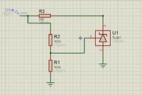
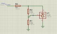
i create this schematic circuit


V Pin 3 to ground=1.91
Vref pin 1 to ground=2.54
:shock:

what is my fault?is it not the similier circuit to SMPS feedback output?


but it works fine

V Pin 3 to ground=5.2
Vref pin 1 to ground=2.54
 
Last edited:

Hi again
It is a simple thing , and if still it isn't clear , i think my explanations weren't good .
Again :
We have an out put . and we have a TL431 , and a series opto coupler . right ?
And TL431 , need at least 2.5 volts in it's reference pin . right ? and you can do an interesting thing ! if you need 30 volts , you can use two resistors . thus instead of 30 volts , v pin 1 will be 2.5 volts . right ? thus , if the vout be around 30 volts it will break and your opto coupler will limit the voltage at the break point . right ?
Is that really , hard to understand ? if yes , tell me , please , i'll draw in piece of paper and attach it for you . ok ?
 

if we now assume that o single input and omit the other fraction ((Vout2 - 2.5) / R2 + (Vout3 - 2.5) / R3) we have
(Vout1 - 2.5) / R1 = 2.5 / Rx

example one that R1=47.5 and Rx=2.7 , Vout1=20

(20-2.5)/47.5=.36

2.5/2.7=.92

they aren't the same.
Yes, but in fact you calculated it correctly the first time! Remember you said this:
Vout=2.5(1+47.5/2.7)=46.48 :shock:
That is quite right. If you take away the first two output voltages,then the third one will go up from 20V to 46.48V.

We can check with the other formula:

(46.48-2.5)/47.5=0.926

2.5/2.7=0.926

They are the same.

A notation : you should use a resistor in parallel with the LED of your opto coupler . don't forget it .
Why? There is a resistor in series with the LED to limit the current. Surely that is all that is needed?
 

Dear godfreyl
Hi
That resistor , is prepared to provide a transient bias for TL431 . you can see the effect of that resistor in practice .
Respect
Goldsmith
 

what is my fault?is it not the similier circuit to SMPS feedback output?
The missing feedback makes the diference.

TL431 can either used as a simpled programmable shunt regulator (as in your second circuit). Then the feedback goes directly from pin3 to to pin 1.

Or as a building block of a SMPS voltage controller. Then the feedback path is through optocoupler and SMPS controller. But your first circuit has no feedback at all.

Regarding the original problem as given by the two schematics in post #1. Godfreyl has already explained that the circuits are feeding multiple output voltages to TL431 and stated
In this case the calculation is more complicated.
But besides involving a more complicated calculation, what's the purpose of the multi-feedback circuit? Did you think about how it works? Does it bring a feature that's helpful for your application?

Strictly viewn, it's impossible to regulate more than one output with a single controller. Usually we call it half-regulated outputs. In the standard configuration, one output is sensed (= regulated) and the other ("half-regulated" ones) hoped to track the regulated voltage with a factor given by the windings ratio.

Of course the concept can't work perfectly and is depending on prerequisites: restricted to flyback mode, minimal load required, good transformer coupling.

The shown circuits are apparently averaging multiple output voltages. This may be useful under special conditions but can't avoid the basic problems of half-regulated outputs.
 

Thanks FVM and godfreyl your perfect explanation.

in this schematic how TL431 work? we can't find any equation that show us the behavior of this circuit? in smps circuit how it works?(it doesn't have any feedback path to himself)because i test it with different type of resistor(i changed the R1 resistor)but the output of Tl431 doesn't change(1.92 volt)
 

As shown, TL431 output (cathode) goes into saturation, apparently around 1.9 V which is the minimum voltage to maintain operation of the regulator. The circuit can be possibly used as a voltage comparator. Now it's indicating Vin > 5V, you can connect a LED to visualize it.

What do you mean with "working" of the circuit? As shown, there's a fixed supply voltage and no feedback. No chance for the TL431 to regulate anything.
 

"You may not vote on any more threads today. " :cry:

wow,you are completely right thanks for your good explanation FVM.i want to know only this point.

and another question is when i put 2 100Kohm resistor in series the output voltage of Tl431 follow the increasing voltage until it wants to be more than Vref*2 and after that it decrease.why it follow the input voltage? because as i know in the comparator mode of op-amp if the voltage at V(+) is infinitesimal bigger than the V(-) it goes to Max saturation and doesn't transfer the input voltage to output

Thanks

---------- Post added at 16:25 ---------- Previous post was at 15:53 ----------

Dear godfreyl

with you equation i calculate but i found Rx different.
gif.latex


gif.latex


as you know the 1.5K is perfect choice.why he use 2.2Kohm?
 

Status
Not open for further replies.

Similar threads

Part and Inventory Search

Welcome to EDABoard.com

Sponsor

Back
Top