Continue to Site

Welcome to EDAboard.com

Welcome to our site! EDAboard.com is an international Electronics Discussion Forum focused on EDA software, circuits, schematics, books, theory, papers, asic, pld, 8051, DSP, Network, RF, Analog Design, PCB, Service Manuals... and a whole lot more! To participate you need to register. Registration is free. Click here to register now.

Current to voltage converter using single supply OP-AMP

Status
Not open for further replies.

Anantha Krishna

Member level 1
Member level 1
Joined
Feb 10, 2011
Messages
41
Helped
1
Reputation
2
Reaction score
1
Trophy points
1,288
Activity points
1,642
Hi,

I am trying to interface a pressure sensor with 4-20 mA output with an ADC. So I have to convert this current to voltage.

But the problem is that I have a single supply of 5V and I want to use LM358 single supply OP-AMP for this conversion. I successfully implemented the circuit using dual supply(+5V and -5V) in inverting amplifier mode, but I was unable to implement using single supply(+5V).

Please suggest how to implement the same circuit in non-inverting mode, so that I can convert this 4-20 mA to +ve voltage.

Thank you.
 

Can you explain what was the problem with the configuration you tried?

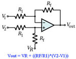
You have a 4-20mA source, you can use a resistor to convert it to a voltage and a differential amplifier to apply an offset and amplify the voltage or maybe you don't need the offset if the output is going to a microcontroler ADC and can be compensated in the code.

Here is a differential amplifier
DiffAmp.jpg]

Alex
 
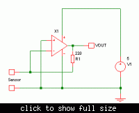
The opamp's input common-mode range includes ground, so you could use a circuit like the one below. The sensor's connections may need to to reversed, depending on whether it sources or sinks current.


Hi,

I am thinking of two ways to implement the above circuit.

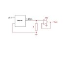
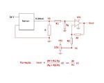
First is in the first image, where I use a resistor to convert current to voltage and use Op-Amp buffer.

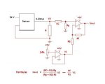
Second is in the second and third image, where I use a differential amplifier to shift my output voltage to get better range for my adc, and use the formula mentioned in the image to calculate the output voltage. I think the circuit in Ck2 is much better than the circuit in Ck1.

Am I correct? Please suggest.


Ckt3.JPGCkt1.JPGCkt2.JPG
 
A typical 4-20 mA current loop configuration uses a positive supply of 15 - 30 V and a ground referenced shunt. Self powered 4-20 mA outputs are often ground referenced.

But its's not the preferred way to pass the full loop current through the input amplifier. Many PLCs are simply using a 250 or 500 ohm shunt as passive I-V converter and no amplifier at all. Alternatively you can use a lower resistance value (e.g. 50 ohm) to reduce shunt power dissipation and achieve better loop supply voltage margin. Then a single supply non-inverting amplifier can scale the shunt voltage to the intended range and optionally apply an offset to get zero output at 4 mA.

P.S.: I see, that your latest post is going the same way. All circuit variants are basically correct.
 
Last edited:
I think the type of circuit to use depends on the kind of sensor you have. Is it OK to just pass the current through a resistor to create a voltage drop, or should the sensor be connected to a virtual ground?
 

The sensor has to be provided with a supply and ground.

I want to use the op-amp to reduce any non-linearity that might occur. The op-amp buffer or differential amplifier will reduce such possibilities and provides good output impedance.
 

Yes, as shown in the pictures in post 4.
 

Status
Not open for further replies.

Similar threads

Part and Inventory Search

Welcome to EDABoard.com

Sponsor

Back
Top