Continue to Site

Welcome to EDAboard.com

Welcome to our site! EDAboard.com is an international Electronics Discussion Forum focused on EDA software, circuits, schematics, books, theory, papers, asic, pld, 8051, DSP, Network, RF, Analog Design, PCB, Service Manuals... and a whole lot more! To participate you need to register. Registration is free. Click here to register now.

How to achieve 60dB PSRR at frequency=1MHz using a two-stage op-amp?? Is it possible?

Status
Not open for further replies.

emeraude

Junior Member level 2
Joined
Mar 2, 2011
Messages
22
Helped
1
Reputation
2
Reaction score
1
Trophy points
1,283
Location
Philippines
Activity points
1,458
Hi! I'm designing a two-stage op-amp and aiming for a 60dB PSRR at 1MHz. Im using simple differential pair for the 1st stage and cascoded common-source at the 2nd stage, and i'm only getting <20dB at 1MHz. What can I do to achieve the 60dB at 1MHZ? Should i change my architecture? But im only limited to two-stage opamp architecture since its what i proposed... By the way, im using tsmc 0.18um technology with 3.3V Vdd... Hope you can help me in this project..Thanks.
 

Hello,

Use large length devices and cascodes for the transistors at the supply rail.

Is it a nmos or pmos input opamp? If it's pmos, don't connect the bulk to the supply but to the source of the transistors.
 
if you need PSRR 60dB@1MHz in simple 2 stage opamp. you need at least 1GHz GBW. usually it is not easy
 
Hi!

Im using nmos input in my differential pair. So by cascoding my differential pair and increasing the length of my transistors would help me achieve a 60dB PSRR @ 1MHz?

In my current design i only have 25MHz GBW and 71dB open loop gain. What to do to further increase my gain and GBW?

What type of two-stage op-amp architecture can u suggest for me to achieve my PSRR spec which is 60dB at 1MHz? Hope you can help me. Thanks.
 

if you need PSRR 60dB@1MHz in simple 2 stage opamp. you need at least 1GHz GBW....
If the opamp can gave a ground reference then it is easier and you don't need as much open-loop bandwidth. The trick is to improve the open-loop PSRR.
 
Hi godfreyl! what do you mean by your first statement? hope you can explain it to me further, i'm not very knowledgable in analog designs... also, how can i improve my open-loop PSRR?
 

Here's the problem:
An opamp generally has two input pins and an output pin. Lets call them in1, in2 and out. The purpose of the opamp is to set Vout = N * (Vin1 -Vin2), where N is the gain.

That's all very well, but what do we mean by "Vout"? Ideally it should be the voltage between the output pin and ground. The problem is that the opamp doesn't know where ground is; the only references it has are the supply rails, and they could be at almost any voltage relative to ground.

Basically, we've set the opamp an impossible task. The best it can do is to set the output voltage relative to one of the supply rails. That's what most opamps do, so the open loop PSRR is zero for that rail, and the closed loop PSRR is limited to the loop gain.

Hence kwkam's comment. If you want 60dB PSRR at 1MHz, you need 60dB loop gain at1MHz, so you need a bandwidth of 1GHz.

Now the good news - if you give the opamp a ground reference, then it's at least theoretically possible for the opamp to set it's output voltage relative to ground.

Let's look at a practical example:
I'm guessing you're working with CMOS, but I'm totally unfamiliar with that, so I hope a BJT example is OK.

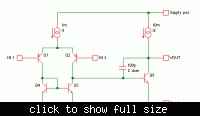
The first pic below shows a dead-simple opamp. Cdom sets the dominant pole. It's a bit early in the morning for mental arithmetic, but with the values shown I think unity gain is at about 30MHz and max slew rate is about 10V/uS.

Notice that the feedback current through Cdom is proportional to the voltage between the output and the negative supply rail, so the output voltage is referenced to the negative rail and PSRR is lousy as usual.

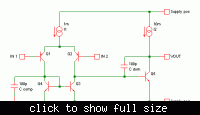
In the second picture another capacitor, Ccomp, has been added for compensation. This feeds current into the mirror proportional to the voltage between ground and the negative rail.

Ignoring the input signal for a moment, we see that the current through Cdom must equal the current through Ccomp, so the voltage across them must be the same i.e. Vout = Vground irrespective of the negative supply voltage. Presto - much better PSRR, limited only by component matching, parasitics and Murphy's law. Even if you only get matching to 10%, that still gives a 20dB improvement in PSRR, and reduces your bandwidth requirement ten-fold.

IIRC, there are some commercial opamps that have a ground pin. It may be worth looking at their schematics to see what they do with it. There's probably other, smarter ways to compensate PSRR than what I've shown.

 
Last edited:

Hi,
So has said in the above discussions, the PSRR can be corrected by either amp or by a filter at the output node. If you need it to be corrected by the amp, then larger BW is required. But filtering can kill your amps BW by a greater factor.
 

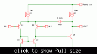
There is also a way to improve open loop PSRR, without adding a ground pin to the chip. If you move Cdom to the position shown in the first pic below, then the output voltage is referenced to one of the input pins instead of to the negative supply rail. PSRR will be better but CMRR may be worse, depending how good or bad it was to start with. Basically, CMRR will now be as bad as PSRR was with Cdom in the other position. Since CMRR wasn't one of your stated goals, that may be OK.

~~~~~~~~~~~~~~~~~~~~~~~~~~~~~

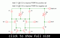
Remember, even if your circuit doesn't have an explicit Cdom, there is some stray capacitance somewhere limiting your bandwidth, and it's those same capacitances that hurt the PSRR.

The second pic below shows a general way to improve PSRR for both rails (at the expense of CMRR again). If you do go about neutralizing the effects of all the stray capacitances like this, you will need an explicit Cdom to define the bandwidth.

~~~~~~~~~~~~~~~~~~~~~~~~~~~~~

If you decide to add a ground pin and fix the PSRR as shown in my previous post, you may still have a problem with PSRR for the positive rail (depending on parasitics and Murphy's law). That can be fixed by adding a small capacitor as needed from the positive rail to either one side of the mirror or the other. Doing that will affect the PSRR for the negative rail as well though, so it would be best to fix the positive rail PSRR first, then the negative rail PSRR.

~~~~~~~~~~~~~~~~~~~~~~~~~~~~~

A final thought: It may be difficult to cancel the effects of stray/parasitic capacitance with fixed capacitance due to manufacturing difficulties* and the voltage dependency of the parasitics. It may be worth trying to fight stray with stray, or taming the parasitics with cascodes where applicable.

* What I mean is: According to my very limited understanding, it's easy to make matched transistors or matched capacitors, but probably not easy to match one with the other.


For PSSR simulation real current and voltage references should be simulated. Also some mismatch simulation has to be done.
With standard process I believe that it is not possible to achieve 60dB PSRR at frequency=1MHz.
 

Status
Not open for further replies.

Part and Inventory Search

Welcome to EDABoard.com

Sponsor

Back
Top