Continue to Site

Welcome to EDAboard.com

Welcome to our site! EDAboard.com is an international Electronics Discussion Forum focused on EDA software, circuits, schematics, books, theory, papers, asic, pld, 8051, DSP, Network, RF, Analog Design, PCB, Service Manuals... and a whole lot more! To participate you need to register. Registration is free. Click here to register now.

[SOLVED] 555 Flashing LED - Help Needed

Status
Not open for further replies.
Re: Calculating Frequency Of Blinking LED

So I have a completed 555 circuit with an LED blinking at 2.5Hz (I believe) with a 1 micro farad capacitor, 1 470k resistor and a 1k resistor. My question is: How would I go about calculating which caps or resistors to use to control the frequency at which the LED will be blinking. For Example, making the LED blink every 30 seconds, every 15 seconds etc...

Have you ever tried to look into something called as "Data Sheet" of 555
 

Download the datasheet for the 555 if you don't already have it. It explains the working principles and formulas for calculating frequencies and time constants. For example, go to https://www.datasheetarchive.com and search for LM555.

Put in some effort to understand what the datasheet says. Then, if there's something you cannot understand, ask here.
 
  • Like
Reactions: Gr3x

    Gr3x

    Points: 2
    Helpful Answer Positive Rating
Ok so I understand how to adjust the frequency of my LED and to calculate the duty cycle with a few easy calculations to find the necessary caps / resistors. Heres what I'm wondering:

With a 555, am I able to adjust the frequency and duty cycle (sorry if wording isn't ideal please bear with me) to a point where the LED can turn on and off at different frequencies? For example could I make the LED turn on for 15 seconds, then turn off for 30 seconds, then on again? I'm having trouble fully grasping the theory behind PWM and the limitations of the 555 timer.

Heres a link to the datasheet I found:

https://pdf1.alldatasheet.com/datasheet-pdf/view/23385/STMICROELECTRONICS/NE555N.html
 

  • Like
Reactions: Gr3x

    Gr3x

    Points: 2
    Helpful Answer Positive Rating
With a 555, am I able to adjust the frequency and duty cycle .....
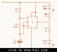
Yes. Here's the circuit you started with, except I've added another LED and resistor.

For D1, time on / time off = (R1 + R2) / R2, so time on is always greater than time off. However D2 will be on when D1 is off and vice versa. You can use D1 or D2 or both.

There's another way to adjust the duty cycle too. Pin 5 normally sits at about 2/3 of the supply voltage, but by changing the voltage on pin 5 you can increase or decrease the duty cycle.

As an experiment, if you have a potentiometer, connect the two ends to battery positive and negative, and connect the center pin (the wiper) to pin 5. That should allow you to adjust the duty cycle over quite a wide range (and change the frequency too as a side effect). A pot of about 10K would be ideal, but other values will work too.

 
  • Like
Reactions: Gr3x

    Gr3x

    Points: 2
    Helpful Answer Positive Rating
Status
Not open for further replies.

Part and Inventory Search

Welcome to EDABoard.com

Sponsor

Back
Top