Continue to Site

Welcome to EDAboard.com

Welcome to our site! EDAboard.com is an international Electronics Discussion Forum focused on EDA software, circuits, schematics, books, theory, papers, asic, pld, 8051, DSP, Network, RF, Analog Design, PCB, Service Manuals... and a whole lot more! To participate you need to register. Registration is free. Click here to register now.

Measurement of current output from solar panel using PIC16F877A, ACS712 hall effect

Status
Not open for further replies.

noel_t

Junior Member level 3
Joined
May 31, 2011
Messages
30
Helped
2
Reputation
4
Reaction score
1
Trophy points
1,288
Activity points
1,592
Dear Friends,

Project Description: Data Acquisition System for Solar Panel

In fact, i need to measure the current from solar panel and display it on the LCD.

I am using PIC16F877A with C language to do so. For the Temperature, Light, and Voltage, there is no issue of reading the sensors and it is working perfectly. However, ACS712 hall effect sensor is mentioned to be a good solution for DC current measurement in the datasheet as well as having a linearity characteristic, but the time i am using it with PIC, it does not give me a true value within at least 0-50 A input ranges.
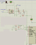
This is the Proteus + ADC codes, Please help me to accomplish this task as well.


ADCON0=CHANNEL3;

lcd_goto(44);
read_adc();
current=read_temp();
current=0.074*current;
current=(current-37.888);
current=current/2;

dis_num(current);
send_char('.');
dis_num(current%10);

send_char(' ');
send_char('A');
send_char(' ');
proteus.jpgproteus.jpg
 

The Error is minimized and reach to the possible actual value in simulation, however practically the circuit is not working and seems something is wrong.
I can pass to you the design simulation in Proteus and MPLAB hi-tech, and please make your comment on what may be the possibilities that practically i am not receiving the same result as simulation.


Dear Friends,

Project Description: Data Acquisition System for Solar Panel

In fact, i need to measure the current from solar panel and display it on the LCD.

I am using PIC16F877A with C language to do so. For the Temperature, Light, and Voltage, there is no issue of reading the sensors and it is working perfectly. However, ACS712 hall effect sensor is mentioned to be a good solution for DC current measurement in the datasheet as well as having a linearity characteristic, but the time i am using it with PIC, it does not give me a true value within at least 0-50 A input ranges.
This is the Proteus + ADC codes, Please help me to accomplish this task as well.


ADCON0=CHANNEL3;

lcd_goto(44);
read_adc();
current=read_temp();
current=0.074*current;
current=(current-37.888);
current=current/2;

dis_num(current);
send_char('.');
dis_num(current%10);

send_char(' ');
send_char('A');
send_char(' ');
View attachment 57241View attachment 57241
 

The Error is minimized and reach to the possible actual value in simulation, however practically the circuit is not working and seems something is wrong.
I can pass to you the design simulation in Proteus and MPLAB hi-tech, and please make your comment on what may be the possibilities that practically i am not receiving the same result as simulation.

I am working on a professional such product with multiple sensors for multiple solar strings. I can give you some tips without giving away the farm.

First, I'm assuming for cost purposes you are using an open loop sensor....as in:
/------\
| |
| |
\___ __/

The circle above is a flat piece of metal in a ring with a gap at the bottom. You put the hall effect sensor in the gap. The wire from/to the solar panels goes through the ring. This creates a magnetic field according to the Right Hand Rule, and this magnetic field is generating a voltage in the hall effect sensor.

Now, typically, like with small honeywell sensors, you are getting 2.5V +/- 0.1V. The offset (2.5V is typically about half the supply of 5V to the hall effect sensor). The +/- part is very small (about 0.1 to 0.3V) and is dependent on the thickness of the metal and the metal type. The metal type is really important (I can't cover that here....there have been books written on it). Use a permalloy or mumetal but make sure it is annealed after you cut it or it will magnetize easily.

Then, you may have to calibrate it by passing multiple currents through it to figure out values for slope and offset particular to that specific Hall Effect transducer.

Finally, I should point out that I've noticed some crosstalk between sensors close together and temperature sensitivity.

Good Luck.
-Donald
 
  • Like
Reactions: noel_t

    noel_t

    Points: 2
    Helpful Answer Positive Rating
I liked your idea Donald. However, I could finally accomplish my task for that project, But I still believe in optimization of our readings from sensors by utilizing the best possible circuitry for the system.
 

Hey noel... can you give me the project softcopy to me
Im doing project on energy meter for solar PV.V&I measure using LEM sensors..
PIC 16f877a for the enrgy calc.
not started the project.planning to do lyk dis
I dont have any exposure to PIC
 

Status
Not open for further replies.

Similar threads

Part and Inventory Search

Welcome to EDABoard.com

Sponsor

Back
Top