Continue to Site

Welcome to EDAboard.com

Welcome to our site! EDAboard.com is an international Electronics Discussion Forum focused on EDA software, circuits, schematics, books, theory, papers, asic, pld, 8051, DSP, Network, RF, Analog Design, PCB, Service Manuals... and a whole lot more! To participate you need to register. Registration is free. Click here to register now.

How to find the values???

Status
Not open for further replies.

prawesh2000

Junior Member level 1
Joined
Apr 23, 2012
Messages
17
Helped
1
Reputation
2
Reaction score
1
Trophy points
1,283
Location
Ronneby, Sweden
Visit site
Activity points
1,407
photo.JPG

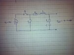
Above is the design of the buck converter I am supposed to design. The given are:

Input voltage (Vin): 9 V
Output voltage (Vout): 3-4 V
Load current (Iload): 5 A
Switching frequency (Fsw): 330 KHz
Ripple voltage (Vripple): 5%
Ripple current (Iripple): 10%

Can anyone help me find the values of the inductor 'L', it's resistance 'RL', capacitor 'C', it's resistance 'Rc'?
Also, I need the values of Ton, Toff, RDson, RDsoff for both the switches S1 and S2.
I am stuck with the values and as soon as I have them, I can plug them in my simulink model and simulate the system. So, please help me find these values.
 

Hi Prabesh

Working it out slowly from first principles......

Resistances:
RC, RL and RDSon should all be very low to get good efficiency. For now, assume zero resistance. Later when you choose actual parts to use, you will have to look for ones with low enough resistances.

Ton and Toff:
If Vin = 9V and Vout = 4V, then S1 must be on 4/9 of the time, and S2 must be on the other 5/9 of the time. (There must also be a little "dead time" in between when both switches are off, but you can worry about that later).

Frequency = 330KHz, so period = 3.33uS.
Ton for S1 = (4/9) * 3.33uS = 1.48uS
Toff for S1 = (5/9) * 3.33uS = 1.85uS

Inductor:
Iload = 5A and Iripple = 10%
I guess that means peak-to-peak ripple in the current through the inductor = 0.5A? If so:
When S1 is on, there is approximately 5V across the inductor for 1.48uS. In that time the current through the inductor must rise 0.5A (or less).

delta I = V*T/L
so L = V*T/delta I
L = 5V * 1.48uS / 0.5A = 14.8uH (or bigger)

Capacitor:
I assume Vripple is peak-to-peak. If so:
Peak to peak voltage change at the output = 5% * 4V = 200mV.
The ripple current through the capacitor is the same as the ripple current through the inductor. Half the time, current is flowing into the capacitor, and half the time current is flowing out.

So for 1.665uS, current is flowing in (or out). The amount of current flowing in (or out) varies between zero and approximately 0.25A, with an average of 0.125A. During that time, the voltage across the capacitor must change by 200mV (or less).

delta V = I*T/C
so C = I*T/deltaV
C = 0.125A * 1.665uS / 0.2V = 1.04uF (or bigger)

Hope that helps get you started.

Regards - Godfrey

p.s. When you simulate the circuit, load the output with a resistor, not a current source, otherwise the LC will ring badly. Later, when you add resistances, they will help to damp the ringing.
 
Last edited:

Thanks Godfrey! But I need to design the converter in real life, so I need to take Rc, RL, Rdson, Rdsoff, etc into consideration. What changes does it bring in the formula? Or we need to do it all over again?


Also please show me the derivation of all the formulae. My teacher wont accept just the formula, he asks for the derivation too.
 

Also please show me the derivation of all the formulae. My teacher wont accept just the formula, he asks for the derivation too.
What derivation?

"L = V*T/delta I" and "C = I*T/delta V" are about as close to the fundamental definitions of inductance and capacitance as you can get. I showed you how to work everything out from first principles.

Have you done any simulations yet?
If you run a simulation and look at the voltage and current waveforms, you will understand how it works.

If you understand it, you can explain it to your teacher.
 
Last edited:
I had to spend a lot of time running simulations, before I could comprehend the operation of a buck converter (also boost and buckboost types).

I particular found the Falstad simulator to be helpful. It is animated. I use it as an alternate to my own homebrew simulator.

https://www.falstad.com/circuit/

Click 'okay' in the window asking to load the applet. You can create a circuit to look just like your schematic.

----------------------------

You are looking for the correct value inductor whose time constant is such that it will ramp up to several amps while switch 1 is closed. This current powers the load and load capacitor.

When switch 2 is closed, the coil is supposed to discharge several amps, maintaining power to the load and load capacitor.

Both events occur inside one 330 kHz cycle.

Assume an inline resistance of 0.1 to 2 ohms while charging the coil.

Assume a very small resistance for the load capacitor. Try .01 ohm (a reasonable figure). Most likely it's to make the simulator happy.

Attach a load of 0.8 ohms. ( 4V / 5A )

Try various values for components.
Look at some buck converter projects on the internet.
Look up threads related to 'buck', using this board's search.

---------- Post added at 13:04 ---------- Previous post was at 12:52 ----------

Also:

* The figure for ripple current means that the coil does not fully discharge. It is always conducting to some extent. This makes for subtleties in behavior that we cannot be expected to understand until we observe waveforms in various experiments.

* A real circuit will use a mosfet/transistor for switch #1. Typically switch #2 is a diode (fast response type).
 
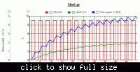
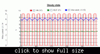
Here is a simple simulation to show you what the waveforms look like.

When you take the resistances into consideration, it will make very little difference. The C and L stay the same. You may have to change Ton and Toff slightly the get exactly the right output voltage.

edit: If this is controlled by a microcontroller, you can probably adjust the timing in software after it's built, or even allow variable output voltage.

 
Last edited:
Dear Prabesh
Hi
What is your exact problem in PI controller ? if you tell me a bit more explanations , thus perhaps i can help you .
Best Wishes
goldsmith
 

I think i sent you an email , some days ago , it consists a reference . so you can find your desired things about PI controller , simply . did you see them carefully ?
 
Status
Not open for further replies.

Part and Inventory Search

Welcome to EDABoard.com

Sponsor

Back
Top