Continue to Site

Welcome to EDAboard.com

Welcome to our site! EDAboard.com is an international Electronics Discussion Forum focused on EDA software, circuits, schematics, books, theory, papers, asic, pld, 8051, DSP, Network, RF, Analog Design, PCB, Service Manuals... and a whole lot more! To participate you need to register. Registration is free. Click here to register now.

CC/CV for smps circuit : uc38xx

Status
Not open for further replies.

Mithun_K_Das

Advanced Member level 3
Joined
Apr 24, 2010
Messages
899
Helped
24
Reputation
48
Reaction score
26
Trophy points
1,318
Location
Dhaka, Bangladesh, Bangladesh
Activity points
8,254
I made a smps battery charger circuit before where I found some problems (posted before). Now I want to start again with uc3843B. But in this time I want to add CC/CV feature with the circuit. Can you give me any suggestion for this?
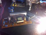
 

Almost a forward type computer psu consist of UC3842.
Can you explain CC/CV features?
As i know a smps charger have features of charging adjust and float (output ) volts control.
Float voltage means 13.5v to 14v for wet lead acid battery and 13.8v to 14.4v for VRLA(dry type) battery.
And initial charging current for wet battery(discharged) should be 1\10 amp of battery,s total capacity.
For example if battery,s capacity is 100Ah charging current should be 10amp.
And if we set float voltage at 14v.
When you connect charger,s terminal to battery,these voltage will dropped and become near battery,s voltage.
e.g if at that time battery,s voltages are 11.5v.
You can measure they become 12v.now we can measure max charging current.
Now charging operation is on the way.
Battery,s voltages will increase and charging current will decrease gradually.
When these voltages will reach at 14v(equal) to chargers output volts.
Charging current will be 0.2 amp (200mA).
 

CC means Constant Current and CV means Constant Voltage. That means, if the output is rates as 15V/10A then either o/p voltage will be constant 15V (+/- 20%) or Current is constant when o/p is overloaded. This is CC/CV feature. In case of battery charger, if the battery is too low ie < 10V then the charge will operate in CC. and whenever battery voltage rises up to 14.25V the charger have to operate in CV so that a little amount of current is maintained after full charge.
 
  • Like
Reactions: pnjbtr

    pnjbtr

    Points: 2
    Helpful Answer Positive Rating
Yes charger i mentioned in my above thread,i think fulfill CC/CV features.
As i observe in start it provides 10 amp after 3 or 4 hours it decrease charging rate.
And float voltage almost 14v still on battery terminals with only 0.2 amp charging current.
It also have trim pot that can change out volts 13.8, 14 and 14.4.
And second trim pot is for adjusting charging current.
But that charger is consist of TL494 chip and 358 op-amp for led indicator.
Your need is UC3842.
I think we should study attached application note.
It also have 5 volts winding in it along with 12v.
We can use only 12v winding in transformer.
Fair child recommends 7 turns for 12v,but our need is 14 to 14.4v.
So we can increase 1 turn extra (8 turns instead of 7) for 14v.
This circuit is for 12v smps.
I hope with some modification we can use it as a battery charger.
we can use a current limiter resistance in series of battery bus bar.
And dropped voltages in resistance can be sense with a op-amp.
 

Attachments

  • 3842 p.supply.pdf
    65.7 KB · Views: 441
Last edited:

thanks for your help. Did you ever try this circuit? I don't need the other windings for -12V && +5V. What is the transformer size? Is this EC40?
 

They recommend EER3542.
But EC40 is also called EC3540.
Because width of E is 40mm and height total of E is 35mm.
Sure we can use EC40 with same turns.
I did not tried it till now.But a friend of mine is saying that he is using it successfully since one year.
As i remember last year i modify a pc supply into a battery charger.
That supply was with Uc3842,Tl431 and pc 817.
That charger is still working in same casing( PC PSU).
If you not intended to use 5 volts.
Wind transformer with primary 50 turns.
8 turns for 14 volts and aux for uc3842 vcc.
 

Yes, I've done it. here is my 14V/15A smps battery charger. 04052012303.jpg

Its working excellent, no smoke, no noise. But the heat sink I'm using is less than required. so little bit extra heat is being generated. But totally its nice.
 

Yes, I've done it. here is my 14V/15A smps battery charger. View attachment 73679

Its working excellent, no smoke, no noise. But the heat sink I'm using is less than required. so little bit extra heat is being generated. But totally its nice. 04052012302.jpg
 

Nice work.
You are using FET and Schottky barrier at same heat sink at corners.
You easily can sense which side of heat is extra.
I think Schottky barrier which is in TO-220 shape should produce much heat at 15 amp.
 

You need to decide if you want Storage cap on output to be included in CC limiter or not.
Some PSU's have CC control but surge capacity is greater than CC average limiter.
That depends on criteria for failure. max power (heat) or max safe current for a load.
 

I'm using MUR3020, TO3p size. I'm trying to find what is the main heat source. The capacitor I'm using is special in duty as they claim. brand name: ELNA, LAJ 2200/63.

---------- Post added at 03:43 ---------- Previous post was at 03:35 ----------

Yes, the main source of heat is the diode.
 

What is switching frequency of smps?
 

Diode Tjc ~1'C/W for DC but your heat sink is much higher, When I used 180W open frame PS in a 1U rack , I added thermistor controlled 25mm fan with thin film lexan folded to create wind tunnel.
How much temperature rise / Watts load? efficiency?

I dont see the cap ELNA, LAJ 2200/63, is it correct?
ESR SRF? No heat in coils?
 
Last edited:

As I've seen, temp rises about 65'C at 140W load. below this load, temp is not so much. I used a 3inch fan which made the system just cool as no load. But I want to use no cooling fan.
 

Thermal resistance drops significantly with air speed over surface.
Ignore volume of air moved by fan, it is linear speed that counts over hot spot.
Miniature fan like 25mm with 3 terminal regulator and thermistor to control fan can be quiet.
But you need a plenum near hot surface to move heat.

efficiency vs load plot may indicate opportunity for improvement.
I suggest you use active load with transistor bank and shunt, not nonlinear light bulbs.
 
Last edited:

I made a smps battery charger circuit before where I found some problems (posted before). Now I want to start again with uc3843B. But in this time I want to add CC/CV feature with the circuit. Can you give me any suggestion for this?

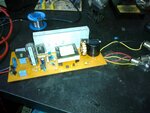
Hi, I did not found your project. Can you send me the link? Tjank you.
 

Status
Not open for further replies.

Similar threads

Part and Inventory Search

Welcome to EDABoard.com

Sponsor

Back
Top