Continue to Site

Welcome to EDAboard.com

Welcome to our site! EDAboard.com is an international Electronics Discussion Forum focused on EDA software, circuits, schematics, books, theory, papers, asic, pld, 8051, DSP, Network, RF, Analog Design, PCB, Service Manuals... and a whole lot more! To participate you need to register. Registration is free. Click here to register now.

[SOLVED] limit on max and min ouput voltage of op-amp.

Status
Not open for further replies.

engrMunna

Advanced Member level 4
Full Member level 1
Joined
Oct 25, 2010
Messages
106
Helped
6
Reputation
12
Reaction score
5
Trophy points
1,298
Activity points
2,071
Hi,
I am using cadence virtuso and spectre. I have a closed loop circuit, which employs an op-amp in the loop. for the time being I am modeling the op-amp by a Voltage Controled Voltage Source (VCVS), with a high gain. For the VCVS , you can set its gain parameter and its maximum and minimum output voltage. When I don't put any limit on the max,min of the output voltages of the VCVC, the circuit works fine and the the output of the opamp is what it should be. The output is well within the range of the power supplies. But when I put the limit on output voltage equal to supply rails, it doesnt work. Any clues?
 

Wrong usage of VCVS statement?

A first hint can be given by elaborating "it doesnt work"...
 

Wrong usage of VCVS statement?

A first hint can be given by elaborating "it doesnt work"...

Thanks for your reply, what do you mean by wrong usage of VCVS statement? Well when it doesn't work, I mean that at the positive terminal of the VCVC, I apply a constant 100mV... then the feedback loop should bring the voltage at the negative terminal of VCVS to around 100mV....and it does if I don't put limits on the output of the VCVC... and the output too then is within the supply voltages.
Now in the VCVS parameter options you can limit the output voltage....so I put a limit on it equal to the supply voltages, When I do this, the negative terminal doesnt follow the positive terminal and the output of VCVC is stuck to one of the rails.
The VCVC is acting like a opamp. I also tried it with a real opamp,(by real I mean a software simulation of a transistor based op-amp and not a model)..and I get the sam result that the output of opamp sticks to one of the rails.
 

Silly question: Exceeds the product (100 mV*gain) the power rails?
 

I also tried it with a real opamp,(by real I mean a software simulation of a transistor based op-amp and not a model)..and I get the sam result that the output of opamp sticks to one of the rails.
In this case, there's apparently a problem with your circuit. You should show it.
 

I got a feeling that the opamp output needs a voltage higher than its limits in order to regulate the feedback to your "100mV". In other words, it's behaving exactly like as expected.
 

Silly question: Exceeds the product (100 mV*gain) the power rails?

yes it does exceed but that shouldnt' matter should it?

---------- Post added at 17:59 ---------- Previous post was at 17:58 ----------

I got a feeling that the opamp output needs a voltage higher than its limits in order to regulate the feedback to your "100mV". In other words, it's behaving exactly like as expected.

No, becasue when I dont put a limit, the circuits regulates the output voltage to 100mV and the output of the opamp is also within the supply rails
 

yes it does exceed but that shouldnt' matter should it?

Is my understanding correct:

The product Vin*gain (Vin= dc voltage) exceeds the power rail - and you are surprised that the output hangs on the supply rail ???
 

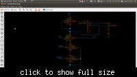
Well here is the circuit
I mean I want the drain voltage of M11 to be equal to 100mV as the current changes through the transistors. When I don't put a limit on output voltage of E7...the Vdrain of M11 is 100mV and the gate voltage of M11 is well with in the supply rails.

P.s don't mind the bulk connection to the drain of the M11...thats on purpose.
 

Well ... E7 is in positive feedback.

I dont understand how is it positive feedback? If output of E7 increases...the Drain voltage of M11 Increases thereby reducing Vin and decreasing E7 output?

---------- Post added at 18:17 ---------- Previous post was at 18:16 ----------

Is my understanding correct:

The product Vin*gain (Vin= dc voltage) exceeds the power rail - and you are surprised that the output hangs on the supply rail ???

Well initially even if it does go to the supply rails...then the feedback should regulate it back. Please see the picture I attached in one of the posts below..
 

By tieing the body like that, there's a diode path from Vdd to your output. Are you sure this drop is less than 0.7V? What's your Vdd?
Also, when output of E7 increases, drain voltage of M11 decreases. This increases Vin, which further increases E7 output.
 
EngrMunna, your description (post#1) was rather confusing: I have a closed loop circuit, which employs an op-amp in the loop.

Note: If you have one single opamp and a passive feedback circuit you have "one opamp in the loop". That was what I have assumed from your description.
Now, you diagram shows a different configuration with TWO amplifiers (active feedback).
Remember: A clear answer requires a clear question!
 

By tieing the body like that, there's a diode path from Vdd to your output. Are you sure this drop is less than 0.7V? What's your Vdd?
Also, when output of E7 increases, drain voltage of M11 decreases. This increases Vin, which further increases E7 output.

You are absolutely right! Thanks I switched the inputs of E7 and it works!

The voltage swing at the drain of M11 is quite small like from Vdd to (Vdd - 300mV) So it shouldn't turn on the diode from the P-substrate to N-type body of M11.

---------- Post added at 18:43 ---------- Previous post was at 18:39 ----------

EngrMunna, your description (post#1) was rather confusing: I have a closed loop circuit, which employs an op-amp in the loop.

Note: If you have one single opamp and a passive feedback circuit you have "one opamp in the loop". That was what I have assumed from your description.
Now, you diagram shows a different configuration with TWO amplifiers (active feedback).
Remember: A clear answer requires a clear question!

Thanks LvW and checkmate for your help guys! its solved now
 

Status
Not open for further replies.

Similar threads

Part and Inventory Search

Welcome to EDABoard.com

Sponsor

Back
Top