EEPC
Newbie level 6

Hi guys,
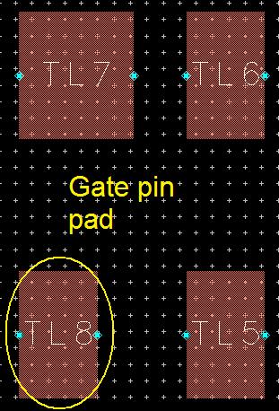
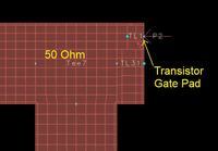
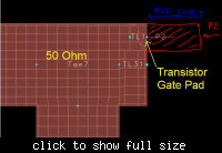
I have a question about doing layout in microstrip. If I have a 50 ohm line that I want to attach to the gate/drain/source pins of a transistor package, can I just solder the transistor on a corner of the 50 ohm line? Or do I have to create a short length of line with width that matches the width of the package pins and then connect the narrow line to my main 50 ohm line? This seems to create severe junction effects that affect overall performance, but I'm not sure what the effect of attaching the pins at one corner of the 50 ohm line would be. This should produce less junction effects, but then the pins can't be aligned in the center of the microstrip line.
What is typically done in layout for connecting transistor pins to input/output microstrip lines?
Thank you!


