Continue to Site

Welcome to EDAboard.com

Welcome to our site! EDAboard.com is an international Electronics Discussion Forum focused on EDA software, circuits, schematics, books, theory, papers, asic, pld, 8051, DSP, Network, RF, Analog Design, PCB, Service Manuals... and a whole lot more! To participate you need to register. Registration is free. Click here to register now.

ARM7 LPC2148 Development Board

Status
Not open for further replies.

A.Rashad

Member level 4
Member level 4
Joined
Jul 27, 2011
Messages
69
Helped
6
Reputation
10
Reaction score
5
Trophy points
1,288
Location
Pune
Activity points
1,792
Hello,
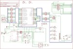
I have design a schematic for LPC 2148 Board , But its not working , I am attaching the
Schematic pdf , please suggest, I t has one programming connector , 2 Uart connectors for GPS and Zigbee , 1 3 pin Battery connector.
When I am trying to burn code using Flash magic , it gives error "Fail to Auto baud" my board's Power LED is glowing.
I am programming by USB to UART converter and programming pins are p0.0 and p0.1.
I have use first 1117 i.e U3 in schematic as 1117 of 5Volt then I have connected 3.3 volt regulator in 1117 series,
Please suggest which pins of LPC2148 we need to tie up to 3.3 V and which should be to ground , I didi according to data sheeet but its not working,
Please say any mistakes in attached schematic?
 

Attachments

  • Weapon Schematic(1).pdf
    223.6 KB · Views: 152

Hey Rashad,

Are you using a USB to serial convertor in between or so.....


check this out

ISP-LPC-E.png
 

Hey Rashad,

Are you using a USB to serial convertor in between or so.....

hello nikhillife
Yes I am using A ft232 USB to serial converter below link
**broken link removed**


I am connecting RX of this programmer to Rx of LPC2148 and TX to TX , But its not working
 

Are you sure that P0.14 is pulled low so that you enter the bootloader?
You can also try to set the UART baud rate to a low value like 9600.
Your power supply connections are fine.

Check this guide to see is you have missed any step.
https://www.google.gr/url?sa=t&rct=...8-n0DQ&usg=AFQjCNEGzirxv-Iea4LHkWAl_FABRhAxBA

Hello Sir,

I am using this programmer **broken link removed**

which has a BSL pin which I am connecting to P0.14 of LPC2148, Does this programmer will pull low the P0.14 or should i need to add something in my schematic?
 

I had simpler problems becuase of USB to serial convertor. Do you know how to test your serial convertor.. just check whether your Convertor is working fine.

TC
 

    V

    Points: 2
    Helpful Answer Positive Rating
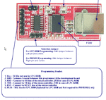
The manual of the programmer is very clear about the connection, Rx is not the receive pin but the pin that should be connected to the receive pin of the mcu, the same with Tx

man.gif
 

forgive me. more me when I refer to Rx and TX, I mean the pin LPC124x and real, not what the motherboard manufacturer says. and write on it, I have and works is by using information from NXP for this and not some other.

Besides that I mention this not because someone commented to me that way, is that it is a plate that I manufactured some years ago and it works just so it is first hand experience
 

I'm not sure what you mean , the developer of the programmer has marked the transmit pin as Rx because it should be connected to the mcu Rx and he has marked the receive pin as Tx because it should be connected to the mcu Tx, are you suggesting the user to connect them otherwise in this specific case?

Is the manual wrong?
 

    V

    Points: 2
    Helpful Answer Positive Rating
Do not know if the manual is right or wrong, I know.
Lpc214x Rx pin is connected to the TX pin of the FTDI.
LPC214x Rx pin to pin TX of the FTDI.
The DTR pin of the FTDI RST operates THROUGH THE 74125.
The RTS pin of the FTDI operates the P0.14 pin THROUGH 74125
if this is true and everything is ok and in spite of that does not work look no problems with connections possible maybe in flash program settings, baud rates, serial set up, handling the serial port DTR and RTS pins must be to so SPI etc etc.
 

    V

    Points: 2
    Helpful Answer Positive Rating
I'm not sure what you mean , the developer of the programmer has marked the transmit pin as Rx because it should be connected to the mcu Rx and he has marked the receive pin as Tx because it should be connected to the mcu Tx, are you suggesting the user to connect them otherwise in this specific case?

Is the manual wrong?

I talked to manufacturer for this issue and I came across that ,manufacturer has already made a cross connection means he has WRITTEN RxD OF FTDI as TX on connector and TXD as RX on connector , for easy connection to programming header on ARM board.
Now I can flash the code ,
Thanks for support

---------- Post added at 13:43 ---------- Previous post was at 13:41 ----------

Do not know if the manual is right or wrong, I know.
Lpc214x Rx pin is connected to the TX pin of the FTDI.
LPC214x Rx pin to pin TX of the FTDI.
The DTR pin of the FTDI RST operates THROUGH THE 74125.
The RTS pin of the FTDI operates the P0.14 pin THROUGH 74125
if this is true and everything is ok and in spite of that does not work look no problems with connections possible maybe in flash program settings, baud rates, serial set up, handling the serial port DTR and RTS pins must be to so SPI etc etc.

Hello andres,

I talked to manufacturer for this issue and I came across that ,manufacturer has already made a cross connection means he has WRITTEN RxD OF FTDI as TX on connector and TXD as RX on connector , for easy connection to programming header on ARM board.
Now I can flash the code ,

But whatever you said and explained was correct , here manufacturer should clarify these things that he has connected already crossed, so user will not get confused , any way its working now
Thanks for support
 

I talked to manufacturer for this issue and I came across that ,manufacturer has already made a cross connection means he has WRITTEN RxD OF FTDI as TX on connector and TXD as RX on connector , for easy connection to programming header on ARM board.
Now I can flash the code

You mean that up until now it wasn't working because you were crossing the programmer outputs (Tx->Rx and Tx->Rx)?

here manufacturer should clarify these things that he has connected already crossed, so user will not get confused , any way its working now

I think the manufactures is not to blame as the manual is crystal clear, the image I have posted in post #9 is from the manual and describes clearly the connection scheme that the user should apply.
 

You mean that up until now it wasn't working because you were crossing the programmer outputs (Tx->Rx and Tx->Rx)?


I think the manufactures is not to blame as the manual is crystal clear, the image I have posted in post #9 is from the manual and describes clearly the connection scheme that the user should apply.

Hello,

Its true the manual is clear, I apologize for my last comment .
 

is very clear that the manufacturer is correct and it is clear what he wrote.
"But," There customary rules
And we all know also that we usually connect the RX signal to TX and vice versa, but there are some that do different things. I do not know what are the reasons or where the benefits.

For it is clear that if we do things in what common sense suggests we tend to simplify the understanding and the world...............
 
is very clear that the manufacturer is correct and it is clear what he wrote.
"But," There customary rules
And we all know also that we usually connect the RX signal to TX and vice versa, but there are some that do different things. I do not know what are the reasons or where the benefits.

For it is clear that if we do things in what common sense suggests we tend to simplify the understanding and the

world...............


thank you very much for your help andres
 

Status
Not open for further replies.

Part and Inventory Search

Welcome to EDABoard.com

Sponsor

Back
Top