Welcome to our site! EDAboard.com is an international Electronics Discussion Forum focused on EDA software, circuits, schematics, books, theory, papers, asic, pld, 8051, DSP, Network, RF, Analog Design, PCB, Service Manuals... and a whole lot more! To participate you need to register. Registration is free. Click here to register now.
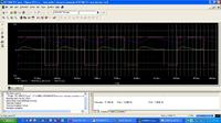
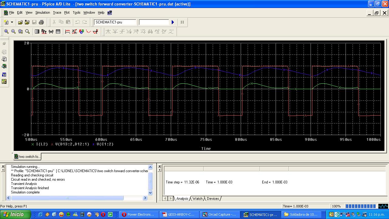
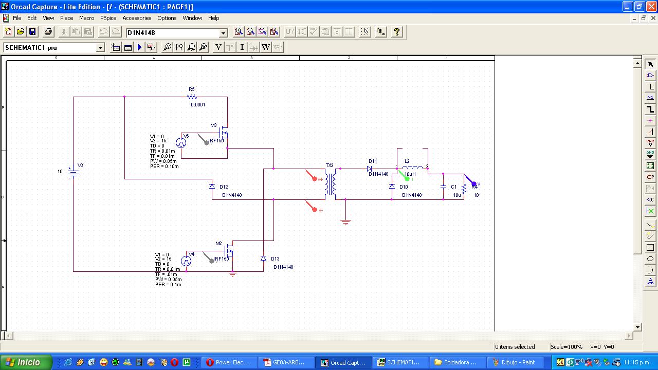
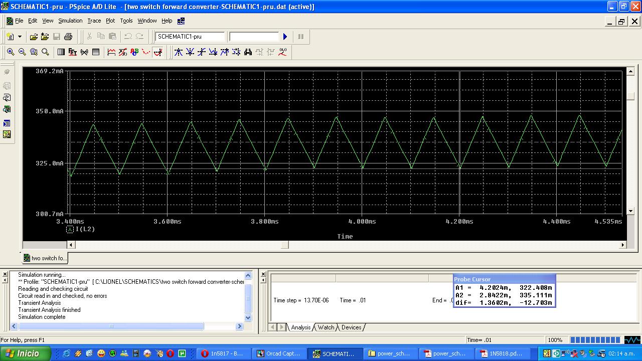
Hello everyone I was simulating a basic two switch forward converter and can't figure out why the output inductor current has this shape (in green)...:shock:
Dear neonwarrior
Hi
The problem is simple . you used 1n4148 diode !! you should use schotky diodes . and in my opinion , it hasn't enough speed and trr and enough capability of current .
Best Wishes
Goldsmith
---------- Post added at 17:42 ---------- Previous post was at 17:36 ----------
BTW : how did you calculate the value of components , all of them are wrong ! i think you selected them randomly !!
The 1n4148 is a pretty fast silicon diode (though it doesn't have a suitable current rating).
I think the slow ringing is due to your switching frequency being close the resonant frequency of the output LC. Either increase the output L or C significantly, or increase the switching frequency.
Dear mtwieg
Hi
Yes i think it's speed is about 9 ns , but what about trr of that ?
and about out put LC network : what do you mean by resonant frequency of that ? i think those are simple LC filter to bulk the energy ( after on time the inductor will discharge to the capacitor , to provide continuous mode ).
Best Regards
Goldsmith
Hello everyone thanks for your help.
And yes, Goldsmith I chose the values randomly.:-D I was just fooling around.
I changed the output inductor's value to 10mH and now the current is a "triangle wave" that's what I was looking for.
Hi neonwarrior
Well .
according to the pressman's book , the out put inductor will given by 3*vo*T)/Ion( maximum current )
And bout the out put capacitor :
And about out put capacitor : it can't be high and it will given by : (65*10^-6)*di/vor and vor is ripple voltage and di is current ripple .
Good luck
Goldsmith
Hi everyone,
I tried 'forward converter' simulation from simplorer 9.0, but I'm not very happy with results and graphs..so please, can you help me and send to me personal composed simulation (if anybody have it)?
Dear Danny
Hi
I suggest you to build your circuit in practice ! simulators can't show you some real events ! ( be sure about it ! )
Best Wishes
Goldsmith
Hi Goldsmith,
I'm built circuit in practice, but I need to compare results from simulation and results from scope.. so, that's reason why am I asked simulation from simplorer.
btw, I have modified circuit from simplorer and now is much better, although there are still uncertainties. If you want I can send file to you.
Plot: Voltage ('V-sec') and current ("I-Seek") and then you will see direction of current (it's inverted).
How is it possible? Where current is passed? The current direction of this can't flow through D1 and D2 :/
This site uses cookies to help personalise content, tailor your experience and to keep you logged in if you register.
By continuing to use this site, you are consenting to our use of cookies.