Continue to Site

Welcome to EDAboard.com

Welcome to our site! EDAboard.com is an international Electronics Discussion Forum focused on EDA software, circuits, schematics, books, theory, papers, asic, pld, 8051, DSP, Network, RF, Analog Design, PCB, Service Manuals... and a whole lot more! To participate you need to register. Registration is free. Click here to register now.

Working of a Voltage Tripler(use of Rectifier Diodes and polar capacitors)

Status
Not open for further replies.

Shayaan_Mustafa

Full Member level 5
Full Member level 5
Joined
Jan 16, 2011
Messages
267
Helped
0
Reputation
0
Reaction score
0
Trophy points
1,296
Activity points
3,213
Hello experts!

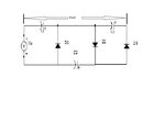
Here is a voltage tripler circuit attached. I want to know the working of this circuit. Assume the circuit is grounded and diodes are ideal i.e. they will not drop any voltage across them typically 0.7v.

STEPS:

1) When a -ve cycle comes, D1 activates and C1 charges to peak voltage(Vp) ideally. While other diodes remain off and no other capacitors will charge.

2) When a +ve cycle comes, D2 is activated and as C1 is already charge, (C1 discharges in this step through D2), so source peak voltage and C1 voltage charge C2 to 2Vp.

3) When again -ve cycle comes, D1 activates and C1 charges to Vp. As C2 is already charged then it will activate D3 and allows C3 to charge upto the voltages that were hold by C2 i.e. 2Vp.

FINAL:

Output will be taken across C1(Vp) and C3(2Vp). Hence, we get 3Vp

Is this all working correct? Help me so that i could design a voltage multiplier that gives 5 times output of voltage source.

Thanks.**broken link removed**
 

Attachments

  • Untitled.jpg
    Untitled.jpg
    27.3 KB · Views: 138

Thanks for reply goldsmith.
Cockcroft-Walton generator or multiplier is an application for which that i have posted.

So therefore I need a discussion on the topic and I posted it here.

Kindly discuss it here. Tell me working is correct or where I did wrong??

Thanks .
 

The circuit is correct.

You can extend it by duplicating the right side block comprised of two diodes and two capcitors and adding it to the right side. Due to the series connection of capcitors, the output resistance will increase however, you get more voltage and less current.
 
Again Hi
And sorry for delaying to reply .
Yes , i'm agree with FvM . and your circuit is correct . and about current if you increase the capacity of your capacitors , the current can increase , but the valuse of capacitors won't be reasonable for high currents . and for higher currents , you'd better to use a simple Boost converter .
Best Wishes
Goldsmith
 
@FvM and goldsmith.

From circuit you mean my steps are correct?

Did you read steps for circuit operation carefully?
 

You have been asking, if the circuit is working. That's the case.

The operation description is basically O.K., but not exact. I don't agree to the sequential step description. It takes more than three "steps" to charge the capacitors fully.
 

You have been asking, if the circuit is working. That's the case.

The operation description is basically O.K., but not exact. I don't agree to the sequential step description. It takes more than three "steps" to charge the capacitors fully.

fully.. but above I mentioned that assume diodes are ideal so the capacitors will charge to the peak values in each cycle.
 

The operation description is basically O.K., but not exact. I don't agree to the sequential step description. It takes more than three "steps" to charge the capacitors fully.

@FvM. Will you justify the bold statement quoted above? Please.
 

The output voltage is approaching the final value in a geometric progression, because the capacitor charge added in each input voltage cycle is divided between multiple capacitors. You'll noticed that the charging process becomes slower if more capacitors are involved.


Attachments

  • Voltage Multiplier.zip
    1.6 KB · Views: 134

This multiplier is a cascade (or Villard) type. It consists of three diode-capacitor pairs, each of which is referred to as a Villard cell.

I will make an animated simulation of this tripler (along with 1 or 2 others). I'll plan to put the video on Youtube in a couple days.
 

@FvM

Thanks I got your point. And want to ask, which simulator did you use? Name please.

Thanks.

---------- Post added at 20:05 ---------- Previous post was at 20:05 ----------

This multiplier is a cascade (or Villard) type. It consists of three diode-capacitor pairs, each of which is referred to as a Villard cell.

I will make an animated simulation of this tripler (along with 1 or 2 others). I'll plan to put the video on Youtube in a couple days.

Thanks BradtheRed. I am waiting for your response.
 

Is it better than Multisim or Altium designer?
Hi again
Surely yes , i think . because the spice series are more close to the real than the others.
Good luck
Goldsmith
 

Status
Not open for further replies.

Similar threads

Part and Inventory Search

Welcome to EDABoard.com

Sponsor

Back
Top