Continue to Site

Welcome to EDAboard.com

Welcome to our site! EDAboard.com is an international Electronics Discussion Forum focused on EDA software, circuits, schematics, books, theory, papers, asic, pld, 8051, DSP, Network, RF, Analog Design, PCB, Service Manuals... and a whole lot more! To participate you need to register. Registration is free. Click here to register now.

SMPS Charger with UC3842 (12V 8A)

Status
Not open for further replies.

kg300

Member level 3
Member level 3
Joined
Sep 21, 2007
Messages
67
Helped
62
Reputation
124
Reaction score
67
Trophy points
1,308
Location
RY Khan - PAK
Activity points
1,852
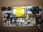
Hi, this is a SMPS charger based on uc3842 chip and deliver 12V 8A output. the problem is that the supply voltage of 3842 VCC are oscillating and i couldn't fix it at 16V and supply cannot start because 3842 ON volt are 18V. when I remove the chip from circuit it goes to 18V accurately. I tried without transformer but Vcc are not ok. Do it work only with the startup circuit (a resistor connected to the 300VDC)? I change 3842 twice but the problem is same. anybody solve the problem.
Thanks.
View attachment 3842.bmp
 
Last edited:

Use a 3845 which does not need 18VDC to start .
It will work with 9VDC inputs minimum.
All the pinouts and ckt design are the same .
 
  • Like
Reactions: Adam Chahab

    Adam Chahab

    Points: 2
    Helpful Answer Positive Rating
    V

    Points: 2
    Helpful Answer Positive Rating
18V is only for startup when ic is not drawing significant current and it is provided from mains rectified voltage through a resistor charging a capacitor. When ic starts oscillation, it draws more current. For a small time charged capacitor will provide current. When voltage on capacitor lowers than 10V, ic turns off until capacitor is again charged above 18V, cycle repeats again.
the problem is that the supply voltage of 3842 VCC are oscillating and i couldn't fix it at 16V
So oscillation is natural response. It is not necessary to fix voltage to 16V. Once started, ic will work down to 10V.
Your problm is that you are trying to evaluate without transformer. Transformer has a seperate special winding, which is necessary for continutios operation. As soon as oscillation starts, voltage developes on this winding and after rectification provides ic with required voltage with high current.

**broken link removed**
 
Last edited:
Thanks friends
 
  • Like
Reactions: neppali

    V

    Points: 2
    Helpful Answer Positive Rating

    neppali

    Points: 2
    Helpful Answer Positive Rating
The core used is ETD39 as the unit is just 100watts (P=12vx8a).With experience in the primary multilayer windings ,this can be further reduced to ETD34 ,with higher flux density 4KGauss .The core is N87 with min. airgap of 10mil. depending on the Al value of core .
For the exact windings and AWG of core as well as secondary windings of magnet wire used , I shall revert back to you after consulting my winder for for confirmation of the same with different layers as this reduces the self capacitance and leakage inductance as well as providing for tight coupling .
 

The 4007 diode in the schematic - is that 1N4007 or UF4007? You should use UF4007. What is the auxiliary voltage? You probably have too low an auxiliary voltage?
 
hello this is kunal
i constructed pcb as schematic everything goes well but after sometime the mosfet T5 gets heated and blows Off again and again,i tried to find the reason and found that the transformer i used went to saturation and it also get heated after along time.The winding for transformer i used was,
primary-28SWG-26turns
secondary-28SWG-4strands 10turns
primary-28SWG-26turns
auxilary-28SWG-2strands-7turns
and i used UC3843 as pwm controller
please tell me the reason why the mosfet blows off and if it is the fault of transformer then please specify the winding ratio of transformer.
 
If transformer core is good for hi frequency then check for operating frequency, it may be low.
 

@kunal,
You need to provide some more info:

Frequency at which UC3842 is running
Minimum input voltage
Output voltage
Maximum output power
Ferrite core used

Probably, your transformer saturates because the flux density is way too high. You most probably need to increase the number of primary turns.

Hope this helps.
Tahmid.
 

You shall need to increase the airgap for reduction of saturation.The freq used is around 65KHz.for 3842-5.However , if the Mosfet blows ,snubber protection is to be increased.
If there is heating , there need to be two things ,source resistance increase for peak current trip.
What Mosfet have you used , pl. check for the Rds ON impedance and max. current capability IDS.
 

hello everybody,
thanks all for your suggestion,actually when any load or battery is not connected neither mosfet nor transformer gets heated,but as i connect a load or battery the mosfet and transformer starts getting heated and after sometime mosfet as well as current sensing resistor boths breaks down.
some of the information related to charger are,
Operating frequency 60-65KHz,
minimum input voltage-90VAC
output voltage-18VDC
Maximum output power-100W
and the mosfet i used is 2SK2645
 

Your transformer saturates and acts as a resistance. The resistance of the winding is very small. So you get a huge current flowing through. This causes the MOSFET and the shunt resistor to be damaged.

Did you use air gap? How big an air gap did you use? What is the inductance of the primary winding?
 
For a 100W device the Mosfet used is very limited in the power dissipation.
The currents used for peak current of 15Amps to 20Amp need be put in.Further , 600VDC MOSFET has a higher Rdon of 1.2ohms and will heat up more .
Prefer to put IRFP360 or 460 which have 450VDC/16Amps /0.27 ohms .
You have max input of 265VAC which gives 375VDC across bridge unloaded .As such ,400-450VDC mosfets are suitable .For lower range of 90VDC the avg. current is1.2Amps and PF of 0.7 gives peak currents needed as 1.8Amps ..10x1.8Amp=18Amps min before shutdown to toff.
The low Rdon is 0.27 nom. gives 4watts at peak load .and heating goes quite low .Kindly send me data on the primary inductance too.
 

For a 100W device the Mosfet used is very limited in the power dissipation.
The currents used for peak current of 15Amps to 20Amp need be put in.Further , 600VDC MOSFET has a higher Rdon of 1.2ohms and will heat up more .
You have max input of 265VAC which gives 375VDC across bridge unloaded .As such ,400-450VDC mosfets are suitable .For lower range of 90VDC the avg. current is1.2Amps and PF of 0.7 gives peak currents needed as 1.8Amps ..10x1.8Amp=18Amps min before shutdown to toff.
The low Rdon is 0.27 nom. gives 4watts at peak load .and heating goes quite low .Kindly send me data on the primary inductance too.

The MOSFET can dissipate upto 50W. That's completely fine since he won't have this much loss for a 100W circuit (at least, he shouldn't).

At 90V AC, he has 127VDC. 100W load at 90VAC input gives peak current of (5.5*100)/127 = 4.33A. The device chosen can handle upto 9A and this is enough margin.

Power loss through conduction loss is another factor and yes, using a MOSFET with a lower RDS(on) will give lower conduction loss.

With max 265VAC that gives 375VDC, 400V MOSFET is not really safe and you have to consider spikes and voltage transients and provide enough headroom so that the maximum voltage across the MOSFET after being clamped by the snubber/clamp circuit is lower than the maximum VDS. 450V may be good, depending on the design of the clamp circuit. It would be safe to use a cheap 500V device. The 600V device is fine, but if the OP wants to lower conduction losses, he may look at cheap 500V common MOSFETs such as IRF840.

Hope this helps.
Tahmid.
 

Like your conclusions.However , the mosfet protections are OK if the core does not saturate and inductance drops.It may be better to have increase in primary turns and increase airgap to increase the margins and reduce on the sharp transients with close pri to sec couplings .
Furthermore , a 400-450Vtransorb from drain to ground and a small 47pf from drain to supply +ve will positively help.
 

It may be better to have increase in primary turns and increase airgap to increase the margins and reduce on the sharp transients with close pri to sec couplings .

Yes.
Mr Kunal, however, is yet to provide us with details such as the primary inductance and air gap so that we may further assist him.
 

primary inductance is the 600-650uH.
leackeg inductance is 7uH.
Voltages on Pin 3 of LM393 are 0.16V for limit the current on 8Amp.
3842-smps.jpg

I use it with my Sine wave Inverter in automatic mode with adding a rellay. the result is perfect and work from 115V to 240V on 8A to 11A.
smps-700wa.jpg
 
Last edited:
Status
Not open for further replies.

Part and Inventory Search

Welcome to EDABoard.com

Sponsor

Back
Top