Continue to Site

Welcome to EDAboard.com

Welcome to our site! EDAboard.com is an international Electronics Discussion Forum focused on EDA software, circuits, schematics, books, theory, papers, asic, pld, 8051, DSP, Network, RF, Analog Design, PCB, Service Manuals... and a whole lot more! To participate you need to register. Registration is free. Click here to register now.

[SOLVED] Extracting maximum power from low current AC source?

Status
Not open for further replies.

jabberwocky_one

Newbie level 6
Newbie level 6
Joined
Apr 14, 2010
Messages
14
Helped
2
Reputation
4
Reaction score
2
Trophy points
1,283
Location
MY
Activity points
1,406
Extracting maximum power from handheld LED flashlight?

Hello I have got a electromechanical device that I'll be using to gather some data soon.
It's a small hand held generator that lights 2 LEDs. This: (http://i01.i.aliimg.com/img/pb/710/380/403/403380710_296.jpg)
I'd like to know how do I measure the power of this device.

I have seen the usage of piezos using a resistor with high ohmmage (10k+Ω) to act as a load,
and was wondering how do I go about doing this (what Ω do I use).
Do I to measure it like piezo's do?

Can anyone help suggest a method to find the power of this device?
 
Last edited:

For a very-low-power LED the estimated power consumption
P=UI
U= 3.5V (white LEDs)
I=0.02A-0.05A
P=0.065W – 0.1 W
Two LEDs in total =2xP = 0.13W -0.2W
:)
 
For a very-low-power LED the estimated power consumption
P=UI
U= 3.5V (white LEDs)
I=0.02A-0.05A
P=0.065W – 0.1 W
Two LEDs in total =2xP = 0.13W -0.2W
:)

Thanks, so it's an estimated 0.13W~0.2W.
If I were to disconnect them(LEDs) and wire a load across the terminals, how much Ω do I put to as load to draw maximum power ?
I ask the above as I've seen the many piezo papers detailing how they put high kΩ resistors as loads to obtain maximum power from the piezo.
I was wonder if the same could be applied here?

I'm actually interested in their electromagnetic power output.
 
Last edited:

Explanation.
Is this hand held gadget some kind of transmitter ?
What do u want to measure ? how much pwr this gadget needs or it is emitting ?
whats the piezo doing here a load for what ?
 

Device on the picture looks like it includes small magnetic outrunner generator >> ac-generator.
You can measure its output voltage with different sized load resistors and make a graph
of generator output power versus load.
Disconnect all loads from generator , look is there any rectifier diodes.
If rectifier is disconnected you get ac-voltage , with diode connect add filter capacitor
eg. 47µF...470µF and you get dc-voltage

eg. use load resistors 2.2k ... 1k ... 470 ohm ... 220 ohm ... 100 ohm
measure voltage across resistor and calculate current and power in resistor.
I = Umeasured / R and P = Umeasured * Umeasured / R
 
I second kak111's recommendation. I have done the same to find out where the max power point is.

Since your led's are probably in the range of 100 to 200 ohms, consider having smaller increments between your various resistive loads, within that range. Your graph of power output will be bell-shaped. You want to catch its topmost peak.
 
The magnitude of the AC voltage generated by this machine is proportional to rotational speed. That’s why he need to keep constant the pressure applied by the hand to the device, otherwise all set of measurements may become irrelevant. :grin:
 

Device on the picture looks like it includes small magnetic outrunner generator >> ac-generator.
You can measure its output voltage with different sized load resistors and make a graph
of generator output power versus load.
Disconnect all loads from generator , look is there any rectifier diodes.
If rectifier is disconnected you get ac-voltage , with diode connect add filter capacitor
eg. 47µF...470µF and you get dc-voltage

eg. use load resistors 2.2k ... 1k ... 470 ohm ... 220 ohm ... 100 ohm
measure voltage across resistor and calculate current and power in resistor.
I = Umeasured / R and P = Umeasured * Umeasured / R

Since your led's are probably in the range of 100 to 200 ohms, consider having smaller increments between your various resistive loads, within that range. Your graph of power output will be bell-shaped. You want to catch its topmost peak.

Thanks, clear and concise. I'll try this, this afternoon.
Thanks for the suggestion on the 100-200Ω range. I'll narrow it there after I test the others with a larger load.

I've got another question, if I have connect a NiMH rechargable battery as the load, I'm guessing that the load becomes the internal resistance of the battery (0.x ohms)?
Do I add more resistors in parallel to match the impedance of the battery and get highest power point for this device ?
Will the other resistors bleed current away if I do this or will current take the path with least resistance and go towards the battery ?

What's the best way to get most of the power into it ? Or is direct connection, the conventional and best way to do it ?
 
Last edited:

Charging battery is a different case.
When load is a battery to be charged, you need
maximum current output.
ie. with this type of small generators there
is no need to connect any parallel resistor.
(by doing so part of the battery charging current
is converted into heat in resistors )
Still its good to check max. current to battery,
so you can determine whether the rectifier and the winding wire
in coil is properly sized.
 

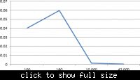
Sorry I didn't have time to thoroughly test it, but here's what I got with one strong push.
The generator is connected to a 1N4007 full bridge, 47uF, and various resistors.

The graph is Power (W) against Load (ohm).
Power was found using V^2/R as suggested by kak111.


The power was half of what mister_rf initially proposed @ 0.06W which is true as the LEDs do light up for about half a second or so.
I couldn't test with more optimised components for the time being as the lab closed till next wednesday. I apologise for this.

I'll properly test it with a bat85 schottky bridge rectifier, and focus more on the 100ohm-300ohm region.

I'll update this thread later next week when I've got the proper measuring tools to work with.

PS: For those watching here's the data I got for now.


V I R
2 0.02 100
3.28 0.018 180
3.44 344u 10,000
3.44 73.19u 47,000

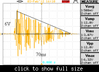
Without the bridge, the AC waveform looks like below:


PPS: How do I change the thread title? Can any mod change it to "Extracting maximum power from handheld LED flashlight?" ?
 

Attachments

  • VoltageOutputHandheldLED.png
    VoltageOutputHandheldLED.png
    4.5 KB · Views: 174
  • PowerOutputHandheldLED.png
    PowerOutputHandheldLED.png
    7.3 KB · Views: 180
Last edited:
  • Like
Reactions: herad

    herad

    Points: 2
    Helpful Answer Positive Rating
Extracting maximum power from handheld LED flashlight?

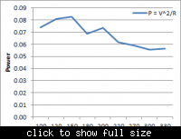
Data obtained. Sorry for the delay.
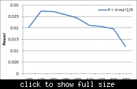
Graph on the left shows the peak output power obtained, right shows the RMS value (didn't manage to set the avg value from the scope).

Circuit was AC Source -> Diode Bridge (BAT85) ->Tank Capacitor (47uF) -> Load.


Table:
Code:
Vpeak	R	P=V^2/R	Vrms	P=V^2/R
2.72	100	0.073984	1.42	0.020164
3.12	120	0.08112	1.81	0.027300833
3.52	150	0.082602667	2.02	0.027202667
3.52	180	0.068835556	1.51	0.025812
3.84	200	0.073728	2.21	0.0244205
3.68	220	0.061556364	2.15	0.021011364
4	270	0.059259259	2.36	0.020628148
4.08	300	0.055488	2.42	0.019521333
4.32	330	0.056552727	1.97	0.011760303
 
  • Like
Reactions: herad

    herad

    Points: 2
    Helpful Answer Positive Rating
Yes, this is certainly the scientific way to do it.

It's natural to wonder 'why is there a trough at the 180 ohm reading?'. There may or may not be a particular reason.

I would feel inclined to perform a second test on that resistance (and the neighboring values as well), just to see if I can end up with a graph that resembles a single mountaintop instead of two.

By the way... Did you make a plot of all three readings (V & A & W)? You'll see that the highest A is delivered at the lowest V. However this does not yield the greatest power. It's non-intuitive, but it can be proved correct, as you have now demonstrated.
 

Status
Not open for further replies.

Part and Inventory Search

Welcome to EDABoard.com

Sponsor

Back
Top