Continue to Site

Welcome to EDAboard.com

Welcome to our site! EDAboard.com is an international Electronics Discussion Forum focused on EDA software, circuits, schematics, books, theory, papers, asic, pld, 8051, DSP, Network, RF, Analog Design, PCB, Service Manuals... and a whole lot more! To participate you need to register. Registration is free. Click here to register now.

NPN to Convert Sin to digital wave

Status
Not open for further replies.

Neyolight

Full Member level 5
Full Member level 5
Joined
Aug 29, 2011
Messages
306
Helped
3
Reputation
6
Reaction score
3
Trophy points
1,298
Location
World
Activity points
3,624
Hi all

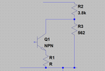
I want to use npn (BF199) to convert the sin wave from my oscillator to a digital wave ( of 2V PK-Pk).

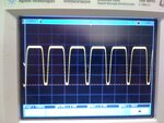
At the moment I am getting something close to digital wave but with 1.6 V P-P.

The base of the npn has a sin wave at 124 KHz with 800mV p-p. The collector is connected to a voltage divider. The emitter goes to ground.

Any ideas as to how I can make my wave look square and increase the Vp-p .

Thanks
 

Attachments

  • npndigital.png
    npndigital.png
    14.3 KB · Views: 80

Hello Dear Neyolight
As i understood , you want convert your sinusoidal to an square wave .
You have some ways :
1- Clipping the sine wave with zener diodes .
2- With a simple comparator such as LM311 or LM339 or LM319 or ... etc .
3- With a transitor amplifier ( as you mentioned at first ).
So for your way , you should play with operating point of your amplifier .
you can do it at class A or at class B .
At class A , your input should be higher than the maximum input signal that is acceptable for your amp ( but it is possible due to the improper design , transistor go to the nonlinear region and destroy all thing !( your waveform )
So i suggest you , do it with a single stage class B amp ( if you want simultaneous square wave you should ad another transistor.
Best Things
Goldsmith
 
Hey Goldsmith - thanks for that.

What do you mean by 'single stage class B amplifier' ?

What is wrong with my design?
 

At first , my mean by single stage class B amp , was , this : if you don't need simultaneous amplitude wave ( minus and plus ) , you can do it with a class B amp , but if it is important to you , you can add another transistor to obtain simultaneous wave .
And about your circuit , you didn't tell , that where's the out and how much is your VCC and where is the base bias network ?!
Good luck
Goldsmith
 
I dont need simultaneous wave. I need a digital wave ( V - 0) .

I am using 9V DC and talking output from the collector. The base receives a sine wave of 124Khz and 800mV.
 

The problem with the circuit such your's is , that you haven't 50 percent duty cycle . do you have any problem with this issue ?
Respect
Goldsmith
 

Im not sure what you mean by that. The duty cycle is not important to me as in the end Im interested in frequency of the signal.
 

Ok so I got it to work. The pic attached shows the output of the circuit. How do I make it perfect TTL ( Equal ON and OFF time) ?

Also this is 3.79V Peak-peak...would it be detected by PIC for frequency measurements?
 

Attachments

  • IMG_0427.JPG
    IMG_0427.JPG
    747.9 KB · Views: 104

Absolutely - you can stop work there!

Here's a snippet from an (arbitrary - the PIC16F88 in this case) PIC data sheet [they're all much the same] indicating what constitutes a logic "high" and a "low":


As you can see, any input voltage < ~0.8V will be regarded as a low, and > ~2V will be considered as high. Your waveform is perfect :)

Don't bother trying to change the duty cycle (without seeing your schematic I'm guessing, but I imagine it'll be a function of your signal input amplitude anyway) as it wont affect your measurements if you trigger/reset a counter on only the rising (or falling) edges. Depending on the PIC you're using, you can either use the timer/capture mechanism to measure the interval between edges or write a nice (lean) interrupt service routine to take snapshots of a free-running counter every time your (edge triggered) interrupt requirements are met.
 
Dear Neyolight
As i saw , your waveform , the rising edge and falling edge isn't good .
Anyway if you want to make it at logic level , according to the it's amplitude , it considered high . and you can give it to a simple not gate , to improve it's shape .
Regards
Goldsmith
 

Status
Not open for further replies.

Similar threads

Part and Inventory Search

Welcome to EDABoard.com

Sponsor

Back
Top