Continue to Site

Welcome to EDAboard.com

Welcome to our site! EDAboard.com is an international Electronics Discussion Forum focused on EDA software, circuits, schematics, books, theory, papers, asic, pld, 8051, DSP, Network, RF, Analog Design, PCB, Service Manuals... and a whole lot more! To participate you need to register. Registration is free. Click here to register now.

Newbie: How this simple 10/24GHz oscillator works? (no DRO, two resistors+microstrip)

Status
Not open for further replies.

Terminator3

Advanced Member level 3
Joined
Feb 25, 2012
Messages
802
Helped
71
Reputation
142
Reaction score
63
Trophy points
1,308
Activity points
9,027
Hello All! I want to build simple oscillator as shown in this article:
**broken link removed**

1) Is it Colpitts oscillator using transistors parasitic capacity? (I read some tutorials from https://www.edaboard.com/threads/85698/ )
2) If it is, How do we know parasitic capacity of transistor. Where is the second "capacitor". Is it good idea to add some smd capacitors?
3) How to determine length L=... between transistor base and R1 welding point (Is it L=WaveLength/2, so we get phase shift of 180. Then transistor itself adds 180 and we get 360 phase shift for proper feedback?)
4) How i can mathematically determine microstrip line lenght and R1 parameters?
5) Can I use this scheme as low-power RF oscillator? How bad is it? Maybe other simple scheme without Dielectric Resonator exists?
6) Can i get RF signal before R1 using SMD or microstrip capacitor and connect it to some kind of antenna?

Thanks!
 

Attachments

  • very-simple-oscillator-10ghz-24ghz.jpg
    very-simple-oscillator-10ghz-24ghz.jpg
    97.8 KB · Views: 311

Hello All! I want to build simple oscillator as shown in this article:
**broken link removed**

1) Is it Colpitts oscillator using transistors parasitic capacity? (I read some tutorials from https://www.edaboard.com/threads/85698/ )
2) If it is, How do we know parasitic capacity of transistor. Where is the second "capacitor". Is it good idea to add some smd capacitors?
3) How to determine length L=... between transistor base and R1 welding point (Is it L=WaveLength/2, so we get phase shift of 180. Then transistor itself adds 180 and we get 360 phase shift for proper feedback?)
4) How i can mathematically determine microstrip line lenght and R1 parameters?
5) Can I use this scheme as low-power RF oscillator? How bad is it? Maybe other simple scheme without Dielectric Resonator exists?
6) Can i get RF signal before R1 using SMD or microstrip capacitor and connect it to some kind of antenna?

Thanks!

The article shows not a 10 GHz oscillator but one that operates at ~1 GHz, and harmonics could be detected by a car radar.
As you have no data on the particular transistor, you cannot design an oscillator with it. I have made similar transistor oscillators; the trick is that you have to make blind experiments with a number of transistors. Only some would oscillate and mathematics cannot help but experience. If you wish, look in an old cavity of an UHF TV tuner. There the frequency coverage of 470-890 MHz was achieved also by experiments.
 
It is an Hartley oscillator in which the tank circuit is a microstrip resonator. The length of the resonator (that can by adjusted moving R1 along the track) its width and the dielectric constant of the substrate are the main parameters to consider to determine the working frequency. Usually the transistor have parasitics that affect not so much the frequency of the resonator.

The performances in terms of phase noise should be acceptable. However I don't have direct experience on this type of oscillator.
 
If you have an intention to design a 10GHz oscillator, why you use this "tricky" oscillator configuration ??
Make it directly 10GHz by using Microstrip-for instance- base grounded oscillator.It's more straightforward..
 
Make it directly 10GHz by using Microstrip-for instance- base grounded oscillator.It's more straightforward..
Oh thanks, just googled it and found some schematic of grounded base oscillator. Actually i thought that 10GHz oscillators are (almost)always done by using DRO, and was excited by "simple" microstrip contruction in my first message.

I have many questions now. But you guys answer so good and so fast, so i feel a little shame asking them right now. Going to read something before.
 

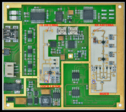
I've found another interesting image at **broken link removed**
quality is very poor, because only small image available, so i made it a little bigger to put my comments.
98_1330252214.gif

i guess that oscillator part is on the left, and some kind of mixer is on the right of this photo (maybe I am wrong, and it is amplifier on the left?). It is difficult to understand how HF comes to mixer, maybe through that holes I marked with blue circles. Two Wilkinson dividers on the right part placed in balanced mixer configuration, 4 black SMD components with 4-LO filters can be Schottky diodes.
Two holes "TX Antenna" and "RX Antenna" can be connected with some quad-patch antenna as in most 10GHz motion detectors.
I do not understand why there are three transistors used and not pretty sure about where is oscillation generator is exactly. I did not found any traces of Dielectric Resonator, but see some strange element near "RX ANTENNA" transistor. I will be happy to see some similar schematic, where only microstrips and some SMD resistors and capacitors are used! Thanks for your attention!
 

Actually i thought that 10GHz oscillators are (almost)always done by using DRO, and was excited by "simple" microstrip contruction in my first message.

It depends what resonator Q factor you need. Higher resonator Q factor means better frequency stability and lower jitter = lower phase noise. DRO is an inexpensive way to design fixed frequency oscillators with decent frequency stability (DRO pills are available with different temperature drift characteristics) and decent signal quality.
 

It depends what resonator Q factor you need. Higher resonator Q factor means better frequency stability and lower jitter = lower phase noise. DRO is an inexpensive way to design fixed frequency oscillators with decent frequency stability (DRO pills are available with different temperature drift characteristics) and decent signal quality.
I thought about using DROs, since I get one woking 10GHz oscillator pcb with parallel feedback based on common emitter scheme npn transistor. But when i tried to copy it design i realised that it is very tricky to find right dro position even in original circuit. It just stopped to oscillate somehow and i do not any serious equipment at home to understand why. As i do not need stability over temperature and time periods, non-DRO idea disturb my mind heavily. I know it is stupid not to use classical straightforward solutions. But i still dreaming about finding out how to do it without DRO. Now i glued old one DRO and planning to use it as reference oscillator: put reference signal and non-DRO oscillation signal together in simple diode mixer to get LOW frequency signal. Then i can analyse it by USB oscilloscope, see how stable it and do some expents. Thats my high frequency amateur dream..
 

Do you say that frequency drifts of some MHz and noisy signal are acceptable? What is the application of your oscilllator?
My application is to measure distance to objects that do not move (no doppler effect). Maximum distance is 10 meters, actually I need only 5, but i used "double rule": If it works better two times, then it easily get that 5 meters. In this case MHz drifts are not acceptable. But what I thought of is it can be self-compensated. Here is my "theory":
Code:
light_speed=299792458 ' light speed in m/s
	light_speed = 299792458
distance_to_object=10 ' maximum distance to object in meters
	distance_to_object = 10

' s - distance to the object
' v - speed of RF wave
' multiply by 2 because wave travels s two times:
bounce_time(s,v)=2*s/v

time_interval1=bounce_time(distance_to_object,light_speed)
	time_interval1 = 0.000000067
' result in seconds

I am going to use Wilkinson power divider, put one half of signal to TX antenna, and the other one into the Schottky 2-diode mixer. RF wave travelling time is small (0.000000067 seconds), so I hope local oscillator will not provide too rapid glitches before transmitter wave come back from RX antenna. Of course some noise will occur. But then I thought a new idea: as i do not need so measure doppler shift, only small distances, then i can do more rapid modulation. More rapid means faster voltage changes in modulation "saw". As modulation is faster, beat frequencies for 1..5 meter distances will be more different. Even if i get some glitch it will be in near-distance readings. But phase noise still occurs on the modulation period, wich is much bigger than 0.000000067s. Modulation period is something between 1..10ms and if big phase noise comes then i get wrong measurement. But then I thought another good idea widely used in spectroscopy: if nothing moves - then accumulate. For example, I get 100 readings, it is only 100*10ms = 1 second. I dream that can get very acceptable results with that heavy modulation and accumulation. After all I want put this "idea" in the matchbox with some low-power ARM microcontroller, Li-accumulator and bright LCD on the back side with some "1,2,3,4,5m" readings. Maybe eraphones jack on the left side to hear some lo-frequency glitches or to connect to PC sound analysis software..

At the moment I did not learned much in microwaves, i stucked with searching proven microstrip design photos. Actually I can't find any images in google that I did not saw before. I have a wide collection of this photos now, some TV/sat recievers, motion detectors, mixers, filters. Most of them using DRO. Of course DRO is "ideal": it is small, it is easy. I read about temperature frequency drifts, and how DRO is good at handling this to few MHz for wide range of temperatures and even smaller, easy feedback design, etc. So tell me can I do it without DROs?

update: i am trying to check simple low-freq oscillator higher harmonics theory (as in my first message), as it seems one of the easiest way, but with many new problems. I was able to hear something on 10GHz, but the signal is very low. Lo-freq oscillator directly connected to the mixer input through capacitor. The other input is voltage regulated DRO at 10GHz. Because signal i can hear is too low, I am afraid it is some interference with other harmonics and/or from power source or computers sound card line-in input, etc.. Can 1GHz oscillation circuit provide lower harmonics somehow? The most difficult part is to tune VCO to find this frequency, i use about 30 minutes warming-up of both circuits and the same time for tuning. Signal analysis performed is 8192 points FFT gives very poor result. If I use a screwdriver to "tune" lower-freq generator by toching vital parts, i hear only noise, so it gives me some hope about true 10GHz harmonic found. Yes, i know, very silly experiment and waste of time..
 
Last edited:

My application is to measure distance to objects that do not move (no doppler effect).

I have worked a bit on these radars for distance measurement, but do not understand what method you want to use.
Above, you calculated the "travel time" of your signal, but how do you want to measure that? You mentioned a low frequency modulation - do you want to detect phase difference on the AM modulation to calculate the distance (AMCW radar)?
 
Last edited:

I want to use classical FMCW approach: because local oscillator frequency sweeps up and down rapidly, rf wave travelling time 0.000000067s on 10 meters will give acceptable beat frequency (maybe about thousand Hertz). It becomes easy because 1..10ms frequency sweep itself is about hundred of MHz. I have no way to check linearity of modulation, so some restrictions occurs such as low precision of distance measurement, poor spectrum of beat frequencies. I hope that this nonlinearity can't make presision lower than +-1 meter. Also I read that frequency modulated approach works good with low-power transmitters and easier to analyse with presence of noise of analog part.

I can't use methods such as detection of phase difference. Wavelenght is too small, and for phase approach to work I will need to "lock" initial position of the object (phase), then somehow "track" this position. Then it will be very sensitive to noise, for example if i walk nearby, then phase tracking algorithm can make wrong decisions. Also I think it needs more powerfull RF transmitter. But the most big problem with that method is that I need to measure distance by myself. Bigger wavelength lead to bad reflection from small objects, so i think it must be something above 4GHz.

I do not know another approaches that can be implemented for small-distance measurement. I read about pulse-method, it works well for long distances, maybe tenth or hundreds kilometers, and certainly need more RF power. For ten meters RF wave will travel too fast ( 0.000000067s) to use pulse method. But for FMCW it is usual comfortable case.
 

I want to use classical FMCW approach

Excellent, this makes sense. You wrote about fixed frequency (DRO) so far, and I did not realize that you have another sweept source to mix both signal, to obtain a frequency ramp in the 10GHz range.

I hope that this nonlinearity can't make presision lower than +-1 meter. Also I read that frequency modulated approach works good with low-power transmitters and easier to analyse with presence of noise of analog part.

The 10GHz FMCW radars that I have been working with had frequency sweep of 500MHz ... 1GHz, with linearized ramp, for a precison of a few cm. The 10GHz swept frequency was created with a varactor tuned VCO.

I can't use methods such as detection of phase difference. Wavelenght is too small, and for phase approach to work I will need to "lock" initial position of the object (phase), then somehow "track" this position.

No, there's a trick. The method would be AMCW. You would use a fixed frequency (in my case it was 24GHz with a DRO oscillator) and apply an AM modulation in the MHz range. Then, you do diode detection of the received signal to recover the modulation signal, and measure the phase difference between modulated (MHz) signal and received signal modulation. The phase depency of the target is now based on the modulation (MHz) signal, so that it's quite easy to measure/evaluate. The disadvantage of AMCW is that it can't deal well with multiple targets, and it's less accurate than FMCW. The only advantage of AMCW is that it is simple (fixed frequency).
 

Compared to state-of-the-art FMCW radars, a few 100 MHz frequency sweep is rather small. But your resolution requirements are also relaxed.

Here's a good manufacturer brochure about level radar, mainly dedicated to FMCW.
 

Attachments

  • HB_LEVELRADAR_e_72.pdf
    1 MB · Views: 199
  • Like
Reactions: Terminator3

    Terminator3

    Points: 2
    Helpful Answer Positive Rating
    V

    Points: 2
    Helpful Answer Positive Rating
No, there's a trick. The method would be AMCW. You would use a fixed frequency (in my case it was 24GHz with a DRO oscillator) and apply an AM modulation in the MHz range. Then, you do diode detection of the received signal to recover the modulation signal, and measure the phase difference between modulated (MHz) signal and received signal modulation.
Oh wow! I did not know that before, thanks =)

You wrote about fixed frequency (DRO) so far
When I alter collector voltage of transistor frequency changes too even with DRO in scheme. It was a surprise. I noticed this effect after some experiments with powering up and powering down npn-transistor: even after powering down some signal comed from mixer for about 2-3ms. I think it is because stabilized power source have many capacitors, and they give some voltage for a short period of time. Then i used computer program for recording sounds i and find out that if some massive object is in front of one-patch tx antenna then i get some sound. For example if it metallic cabinet, i can get some strong sound tones, and this tone grows with distance. I was able to hear it even with interferense from power switching, but modulation length is too short for simple DSP method. Maybe 10-20 points of some tens kHz sampling rate. I thought about adding microcontroller with DAC and put some OpAmp to alter base voltage of transistor. But the bad bart is that my DRO oscillator is glued (welded?) in a big cavity with some unused old schematic. I know it is not right way to change the frequency, and it is better to use varactor and microstrip near DRO as shown here: **broken link removed** (i like this design, but do not like DRO). Now I reading some info on FET transistors, there are some interesting schemes below 5GHz, maybe try them later. It is more simple and can use cheap PCB. The bad part is that many schematics provide only theoretical design, and no microstrip design.

FvM, just noticed your reply, thanks for information.
 
Last edited:

A new idea. Can i use microstrip bandpass filter as a feedback at 10GHz frequency as shown on this page: **broken link removed** ?
Maybe get some good FET or bipolar transistor, etch some filter with 180 phase delay, fed power and see what happen...
also A Wideband, Varactor-tuned Microstrip VCO

update: haha! my dream comes true. Look at this design:
ma.kaist.ac.kr/papers/37.pdf
ap-s.ei.tuat.ac.jp/isapx/2005/pdf/1D1-2.pdf
bye-bye DROs! cool minimalistic design
also good paper Active integrated antennas - Microwave Theory and Techniques ..., can put slave fet transistors.
 
Last edited:

I think something is wrong with your approach. FMCW needs a wideband tunable signal, with linear sweep. It makes not much sense to look at fixed frequency oscillators, no matter if the resonator is DRO or microstrip filter. You need a VCO with decent tuning range and known tuning curve. Typical FMCW systems have built-in circuitry to measure the frequency/tuning curve, and then apply corrections, to ensure linear sweep.

IMO, you will not get anything useful if you use DIY fixed frequency oscillators (no matter how simple the design is) and try to de-tune them a bit, with unknown tuning range and unknown tuning curve.

I have no experience with using microprocessors but yes with various radars.
You can make a simple FMCW radar from a satellite TV LNB available for $15 or so. The Ku-band LNBs have a DRO inside running at 9.75 GHz. You can open the device and modulate the DRO with a small loudspeaker fed by ~1 kHz. Attach an aluminum sticker to the cone and get as close as you can to the dielectric resonator.

Then you can use the mixer in the LNB but the IF amplifier covers too high frequency range, 0.95-2.15 GHz. You will need to connect mixer output first to an oscilloscope, then to an audio amplifier.
You will have to find out how to disconnect the RF amplifiers and connect DRO output directly to the tubular antenna, best where it connects to the mixer.
You can then calculate the audio output frequency for objects at several meters distance, and indicate it on the scope. Later use a simple counter with a display.
 
Status
Not open for further replies.

Part and Inventory Search

Welcome to EDABoard.com

Sponsor

Back
Top