Continue to Site

Welcome to EDAboard.com

Welcome to our site! EDAboard.com is an international Electronics Discussion Forum focused on EDA software, circuits, schematics, books, theory, papers, asic, pld, 8051, DSP, Network, RF, Analog Design, PCB, Service Manuals... and a whole lot more! To participate you need to register. Registration is free. Click here to register now.

How to Display variable 25v DC on 2x16 LCD

Status
Not open for further replies.

aameer

Full Member level 4
Full Member level 4
Joined
May 12, 2010
Messages
216
Helped
33
Reputation
64
Reaction score
32
Trophy points
1,308
Location
Bangalore
Activity points
2,503
Hello friends,
I want to display the voltages between 0-25v Dc on 2x16 LCD.. if i know how to convert 25v into 5v..i can make use of ADC with 8051 / PIC micro controllers . But i am not getting how to convert this 25v into 5v..........
Thanks in Advance
Waiting for quick Response
Aameer
 

You can use a simple Voltage Divider Circuit to convert your 25V(if it is Maximum) to 5V at controller's pin..

And Accordingly use scale factors in your code..


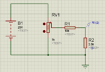
Use this Circuit
Capture.PNG
 

Hi dear aameer*
Did you will to make a voltmeter ?
for this goal there is two way:
make it with micro controller only.
make it with external d/a with micro controller .
which way do you want ?

best wishes
Green tree
 

@greentree
ya i am planning to make DC voltmeter.. My friend has reduced high voltage to 25V DC.So he wants me to prepare some circuit to display the voltage. In his circuit the maximum voltage is 25v..

Can you elaborate the 2 methods and which 1 is good.....
Thanks in Advance

---------- Post added at 19:21 ---------- Previous post was at 19:19 ----------

@arunSharma

Have you used 1K pot ,10k and 2.5k resistor and what is R1(2)..is the output pin feed to ADC....
Can u explain your Circuit
 

I have used 1k POT to just vary the voltage..
You have to just concentrate on the next part of circuit.
You have to scale down your 25V voltage to 5V for Controller

Now Take two resistance
R1*25/(R1+R2) = 5
Use this formula

Assume R1 value
and calculate R2..
This is what i had done..
 
  • Like
Reactions: aameer

    aameer

    Points: 2
    Helpful Answer Positive Rating
Hi dear aamear*
If you will make a voltmeter just with mcu :
you must convert your maximum voltage to 5v .(so i think this isn't very accurate because you can sense for example 12.15v)
If more accurate isn't important for you, this way is good.
But i like say you a way that when you want more accurate it is good!;-)
In way number 2 you have one mcu and one D/A and one op-amp.
The else advantage of this way you can sense mv . because you can have more bit for A/D!

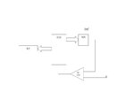
At first you make this circuit :
voltmeter.JPG

Vref is maximum input voltage. total of this circuit is A/D! so your mcu ports define bit of A/D and so define accurate .
Indeed mcu is n bit binary counter , so you must increase the value of port then its value at D/A convert to a analog voltage and in op-amp compared with your voltage. if it be more than your voltage, the out of op-amp is 0v then the number of ports increase ... insofar as the out of the D/A be equal with your voltage, so the out of op-amp will be 1 then if you composed in mcu when this happened the mcu decimal equivalent of the last value of ports put on the lcd you can found the value of your voltage!
 
Last edited:
  • Like
Reactions: aameer

    aameer

    Points: 2
    Helpful Answer Positive Rating
i have not come across DAC so i will check with arun sharma s circuit and will get you guys back..

Anyways Thanks
 

Hi dear aamear*
If you will make a voltmeter just with mcu :
you must convert your maximum voltage to 5v .(so i think this isn't very accurate because you can sense for example 12.15v)
If more accurate isn't important for you, this way is good.
But i like say you a way that when you want more accurate it is good!
In way number 2 you have one mcu and one D/A and one op-amp.
The else advantage of this way you can sense mv . because you can have more bit for A/D!

At first you make this circuit :
voltmeter.jpg

Vref is maximum input voltage. total of this circuit is A/D! so your mcu ports define bit of A/D and so define accurate .
Indeed mcu is n bit binary counter , so you must increase the value of port then its value at D/A convert to a analog voltage and in op-amp compared with your voltage. if it be more than your voltage, the out of op-amp is 0v then the number of ports increase ... insofar as the out of the D/A be equal with your voltage, so the out of op-amp will be 1 then if you composed in mcu when this happened the mcu decimal equivalent of the last value of ports put on the lcd you can found the value of your voltage!

Green Tree is absolutely right..
My Design is not so accurate...
Can u pls explain regarding ur design
 

Hi*
I had very late . excuse me please...
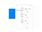
For dac i think this circuit is good (i'm not sure yet!) because you can choose everything for the value of Vref .
DAC1.JPG
For more bit, you must put more transistor and resistor like that picture.
I will be very happy if you say me this dac is application or not.
Oh! im forgot that say this is not . my mean is : if a pin of mcu be high Vout of its transistor is low .so you must count inverse!:roll:
Best wishes
Green tree
 
Last edited:

Status
Not open for further replies.

Part and Inventory Search

Welcome to EDABoard.com

Sponsor

Back
Top