Welcome to our site! EDAboard.com is an international Electronics Discussion Forum focused on EDA software, circuits, schematics, books, theory, papers, asic, pld, 8051, DSP, Network, RF, Analog Design, PCB, Service Manuals... and a whole lot more! To participate you need to register. Registration is free. Click here to register now.
Hi to everybody! I know that this is a simple circuit but I don't have much knowledge with op-amps. Could someone explain me the potential use and difference between these two circuits. Thanks!
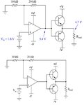
The first circuit uses complementary emitter followers as a buffer/driver. It will have significant crossover distortion. The second circuit includes the transistors in the feedback loop to try to eliminate the distortions due to the the transistor output stage.
As keith has mentioned, both circuits use Class AB emitter followers as a driver.
The difference is that the output for the 2nd circuit is not in the feedback loop and hence will not be regulated.
This means that your "4.7V" will drift with process, temperature, load, supply etc.
Only "5.4V" node will be regulated at 3*Vin.
If you have studied control theory, the 1st is an example of closed loop control, while the latter is an example of open loop control.
This site uses cookies to help personalise content, tailor your experience and to keep you logged in if you register.
By continuing to use this site, you are consenting to our use of cookies.