Continue to Site

Welcome to EDAboard.com

Welcome to our site! EDAboard.com is an international Electronics Discussion Forum focused on EDA software, circuits, schematics, books, theory, papers, asic, pld, 8051, DSP, Network, RF, Analog Design, PCB, Service Manuals... and a whole lot more! To participate you need to register. Registration is free. Click here to register now.

Tone control circuit analysis

Status
Not open for further replies.

Tom2

Full Member level 5
Joined
Nov 11, 2006
Messages
318
Helped
3
Reputation
6
Reaction score
3
Trophy points
1,298
Activity points
3,457
I wonder if someone can help me to analysis the follow tone control circuit.

How is working and what is the purpose of each part
 

Attachments

  • tone_control.jpg
    tone_control.jpg
    141.4 KB · Views: 113

Hi my friend
It is simple. at first step , it used an active filter that based on op amp amplifier with positive gain . And the input used some filters . that you can consider the input signal for one of them ( at one time ) and do summation between the effects of input signals . and thus you can find the AV and Cutoff frequency simply ( super position method for solution).
Best Wishes
Goldsmith
 
Yes i agree this is obvious but i have little confuse (because of the connection ) about what kind of filters are that.
 

First comment:

It's no active filter. It's a variable passive RC filter with a succeeding gain stage. If you omit the gain stage, you don't change the filter operation.

Secondly, some component values like 0.022 pF are surely wrong.

It's looks like one of these classical guitar amp tone controls (if you imagine tubes instead of OP amplifiers). The circuits are very arbitray and don't follow any tone control prototype. In my view, the control capability is poor compared to modern tone controls like parametric equalizers (multiple filters tunable in terms of frequency, gain variation and possibly Q) or also a standard active tri-band tone control (bass, mid, treble).

To evaluate the circuit operation (presumed you have reasonable component values), you can utilize AC analysis of a SPICE variant, e.g. free LTSpice.
 
  • Like
Reactions: KerimF

    KerimF

    Points: 2
    Helpful Answer Positive Rating
Dear Tom
as i told you , try the super position method . try to separate the input filters from each other .
Regards

---------- Post added at 02:41 ---------- Previous post was at 02:38 ----------

Dear FvM
Hi
What do i mean by active? my mean is that the out put of this system , can be higher than input . isn't it?
Respectfully
Goldsmith
 

For instance, the values of R2, R3, R4 and R7 are also important and determine the response of the filter.
Unless it is homework (hence you need to find and solve equations in function of frequency and the pot positions of R2, R3, R4 and R7), I think, as already mentioned by FvM, the best way to play with such a passive filter is by AC analysis simulation. Of course you can still doing it as homework if you have time :)
 
  • Like
Reactions: FvM

    FvM

    Points: 2
    Helpful Answer Positive Rating
What do i mean by active? my mean is that the out put of this system , can be higher than input . isn't it?
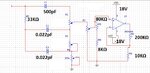
In usual understanding active filter means, that the amplifier is part of the filter design, which is indicated by amplifier parameters (usually a gain) appearing in the transfer function. This also includes "simulated" circuit elements like active inductors or negative resistances. A passive filter cascaded with an amplifier isn't considered as active filter.

If you want to implement complex pole pairs with pure RC (or pure RL) filters, as required by popular filter prototypes (bessel, butterworth, chebychev) for order > 1, you need to go for active filters.
 
Last edited:
Guys please focus to my question which is :
Is obvious that in this circuits there are some filters. My question is what kind of filters are ?

For example the pairs C1 R1,C2 R3, C3 R4 are high pass filters ?????

By using the superposition theorem you must to divide the circuit in sub circuits. What are these sub circuits this is my question.
 

Dear Tom
Did you try super position method? or did you try to simulation that?
Good luck
Goldsmith
 

Status
Not open for further replies.

Part and Inventory Search

Welcome to EDABoard.com

Sponsor

Back
Top