Continue to Site

Welcome to EDAboard.com

Welcome to our site! EDAboard.com is an international Electronics Discussion Forum focused on EDA software, circuits, schematics, books, theory, papers, asic, pld, 8051, DSP, Network, RF, Analog Design, PCB, Service Manuals... and a whole lot more! To participate you need to register. Registration is free. Click here to register now.

How to use a transistor as an amplifier?

Status
Not open for further replies.

Liamlambchop

Member level 2
Member level 2
Joined
Sep 19, 2011
Messages
45
Helped
0
Reputation
0
Reaction score
0
Trophy points
1,286
Activity points
1,738
Hey guys,

I have an arduino which is blinking an infrared emitting diode (IED) at a frequency of 38kHz. The arduino outputs 40mA per digital output pin, and I need about 100mA. I am unable to program the arduino to simultaneously turn on and off 3 pins at 38kHz, so I want to use a transistor to give me the extra current I require.

I have never designed a circuit with a transistor in it before (yes, I'm in the infancy of my electronics education), so I need some help with how to integrate it.

I have two options for extra power sources:

1. Is from the source which powers the arduino itself. This is a 12V, solar panel charged, battery.
2. Is from 2 other pins on the arduino (each pin can output 40mA at 5V).

So, how can I get my IED drawing 100mA using a transistor?

Thanks!!!!
 

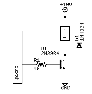
See how to interface with mc : Microcontroller Interfacing

The general idea is like this:- (see above link to customize)
int-switch-npn.png
 

Attachments

  • circuit-to-drive-LEDs-from-microcontroller.jpg
    circuit-to-drive-LEDs-from-microcontroller.jpg
    17.8 KB · Views: 258
Why is it that I should use a 500mA transistor? How do I go about selecting the right transistor for my application, like what specifications do I need to look at?

Would something like this
HTML:
http://www.farnell.com/datasheets/296638.pdf
be ok? I need the transistor to only allow current to flow from the collector to the emitter when the arduino outputs HIGH at the base. How do I find out if this transistor will do that?
 
Last edited:

The nature of silicon transistors is such that the gain falls off substantially long before the maximum current rating is reached. Therefore, wherever possible, it's a good idea to use a transistor with a maximum current rating much higher than that required by the application.

Another thing I'd like to point out is that the online references suggested before do not take into account the large reduction in current gain (or beta) at low Vce. Your aplication requires hard on-off switching which means that the transistor will be in saturation (i.e., at the lowest Vce possible) when it's on. In one of the examples given, the writer bases his calculation of base current on a measured beta of 318. But this was measured in a non-saturated condition and that's not good enough for calculating the base current for hard switching operation. And then there's the matter of tolerance and variations with temperature to consider.

The general rule of thumb is to use a base current equal to Ic/10 for medium beta transistors and Ic/20 to Ic/40 for high-gain transistors. The BC547B used in that article is a high-gain transistor so that for the required collector current of 20mA in that example, the base current should be 0.5-1 mA.

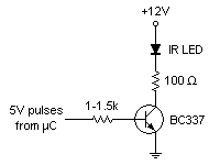
For your application, the BC547B is not a good choice because its maximum Ic rating is 100mA. As already mentioned, the 2N2222 has a max Ic of 500mA (800mA by some manufacturers) and is optimised for switching, but its gain is fairly low and you'll have to drive it with a base current of at least 10mA. A BC337 has the same current ratings as a 2N2222 but has a much higher beta so that a lower base drive can be used. For an 'on' Ic of 100mA, a base current of 3-5mA is appropriate. I suggest the following circuit -

4_1324095997.png
 
Why is it that I should use a 500mA transistor? How do I go about selecting the right transistor for my application, like what specifications do I need to look at?

For your purposes almost any general purpose npn bipolar transistor will do since none of the specs are out of the norm. Generally you need to consider max Ic, max Vce, max Pd=Ic x Vce, switching time, and Hfe or beta ( current gain ). Most general purpose bipolar transistors will have max Ic of between 300 to 800 mA.

Would something like this
HTML:
http://www.farnell.com/datasheets/296638.pdf
be ok? I need the transistor to only allow current to flow from the collector to the emitter when the arduino outputs HIGH at the base. How do I find out if this transistor will do that?

It's not the best choice. Technically the specs are met but only barely. Vce max is only 15V and Ic max is only 200mA. A 2N2222 has Vce of 40V and Ic of 800mA with beta of 300 and Ft of 300Mhz. You should always leave some headroom in the specs or you will be pushing the transistor to an early death.

It is more the design of the transistor circuit that determines what will happen. The specific choice of transistor is mostly based on the maximum needs of the circuit such as Collector current, Collector-Emitter Voltage, Power Dissipation, Switching Speed, etc....The given circuits should perform the task needed. Collector resistor should be 100 ohm to give Ic of 100mA with 12 V supply. The base resistor is not as critical but should be about 1 kohm. Note: the given designs have a switching threshold of about 0.7V - this probably will work but adding a diode in series with the base resistor would make the threshold switch at TTL levels.
 
The 2N2222 and its plastic version PN2222 is a classic product and one of the most popular switching transistors, and I've used it numerous times. But the gain of 300 is only a typical value at 150mA and Vce of 10V. The minimum under those conditions is 100. At 1V, it drops to 50 and 1V is not yet full saturation. The gain (beta) will drop even further at full on condition with a Vce of ~0.5V, and still further at lower temperatures. It's the minimum that has to be considered to ensure proper switching. Which is why rule of thumb dictates Ic/10 as Ib for transistors of that class of gain.

The BC337 I suggested has higher beta at all levels. It is slower than the 2N2222 as a switching device, but I've used it many times at 38kHz and it's fast enough. Of course, the OP stated that his uC can provide up to 40mA of drive current, so a 2N2222 can certainly be used. But IMO the lower drive requirement of the BC337 is preferable as it places less stress on the uC and also reduces overall power consumption.
 
Guys, this is brilliant. You explained it all so well!!!! Thank you so much pj and dart :))) I'm going to go with the circuit you suggested pj. I'm really pleased, I feel like I understand it all so much better.

I'll be buying my transistor from au.element14.com (I'm in australia). Here is the spec sheet for the one I'd choose https://www.farnell.com/datasheets/43666.pdf

I do have one last question: how do I know at what Vbe/Ibe the transistor will switch on, from looking at the specs on the data sheet?

Cheers.
 
Last edited:

I do have one last question: how do I know at what Vbe/Ibe the transistor will switch on, from looking at the specs on the data sheet?

Cheers.

Technically, you need the input characteristic curve of the BE junction which is not supplied on the given datasheet. But for silicon transistors, it is always around 0.6 to 0.7V unless you have multiple BE junctions like a Darlington transistor. Having said that, there is no precise turn on voltage. There is a sharp knee which is generally around 0.6 to 0.7 V. In most simple circuits the exact nature of the input curve is not necessary because the biasing resistors will self regulate the DC base and emitter voltages. In this case, the ratio of the base resistor to the collector resistor ensures that the transistor will be on. Essentially this occurs because the resistors are linear devices and BE junction of the transistor is not. The BE voltage will change only slightly for large changes in the base and collector currents. So you can begin your design by assuming approximately 0.7V across the BE and then calculate the required values of the resistors to ensure the transistor is saturated.

In this case, the collector resistor is set to produce 100 mA when the transistor is saturated. Vce will be low, say 0.1V. We'll assume 0V. The Ired drop will be about 2V (varies slightly with actual Ired and current ) and the supply is 12V. so Rc = (12V-2V)/100 mA = 100 ohm ( you can subtract another 0.1V for Vce if you want but as you can see it will not matter much ).

For the base resistor we start by assuming 0.7V drop across BE when it is on. We should be safe in assuming a beta of 100 for most general purpose npn transistors. As the transistor saturates, there will not be enough supply to allow beta to remain high. This is actually the main reason why beta drops as the transistor saturates. So Ib = Ic / 100 = 1 mA. and the voltage across the base resistor will be 5V-0.7V so Rb = (5V - 0.7V) / 1mA = 4.3 kohms. This is the bare minimum to turn the transistor on and can be unpredictable because of variations in beta and the input characteristic curves. So it is better to choose Rb < 4.3kohms. Since the Arduino can supply 40mA, the minimum value of Rb is 4.3V / 40mA = 107.5 ohms. As you can see 1 kohm should be plenty to ensure saturation and not drain the output of the Arduino.

Let's go back for a moment and see what I meant about saturation supply. At 1 kohm and 1 mA, the voltage across the base resistor is 1V. That means 4V across the BE junction. ( I am assuming of course 5V out of the Arduino which is not actually accurate but good enough for our purposes ). The BE junction would blow with 4V across it. It is rated at a max of 1.2 V. But this won't actually happen because the input curve of the transistor, if we had it, would surely have a Ib >> 1mA for Vbe of 4V. So what happens? beta drops!!! Ib will be larger than 1mA and Vbe will self regulate to match the input curve of the transistor to the required beta. Note: this only happens because we ensured the transistor will saturate by making Rb smaller than 4.3 kohms.

Also Note: none of the above design elements were based on the specs of the transistor other than beta. As I said, general npn transistors almost always have beta > 100 anyways. And, if you had to, you could make this work with a beta of less than 100.
 
You can use the same idea for driving a relay.
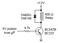
But, you should add a reverse bias diode across the input relay coil to reduce inductive kickback when the transistor switches.
If the relay is a 12V 100mA relay then essentially the same circuit.
 
To add a bit to the good advice given by DartPlayer170: Many small 12V relays have coil resistances of 150 or 400 ohms, meaning that they draw a current of 80 or 30mA respectively. If your relay is the 150-ohm type, the circuit given previously can be used unchanged except for the diode mentioned by Dart. If it's a 400-ohm type, the base drive can be reduced further, and a BC547B can also be used. The base resistor can be about 4.7k.

0_1324278503.png
 
how much current is given from the micro controller when at 5V........?

and can i use 2n2222 for driving this circuitry....?
 

Generally at I/o safe current will be 10mili amp.....check your data sheet ....they generally give the I/O currents.....

Good Luck
 

how much current is given from the micro controller when at 5V........?
About 0.9mA if the output resistance of the uC is low. If the uC output has an appreciable internal resistance, the current will be reduced somewhat but it will still be anough to drive the transistor into saturation.

and can i use 2n2222 for driving this circuitry....?
Yes, but it will be best if you reduce the base series resistor to about 1.5k. This provides a higher base drive current to compensate for the 2N2222's lower current gain.
 

how much current is given from the micro controller when at 5V........?

and can i use 2n2222 for driving this circuitry....?

Depends on the base resistor value.
0.9mA for a 4.7k resistor.
If you use a 2N2222 with a 1.5k ohm it will be approx: ( 5V - 0.7V )/1.5kohm = 2.9mA
That is only approx because output won't be exactly 5V and Vbe will prob be more like 0.8V in reality when transistor is saturated.
For a 2N2222 you should design base current 1/10 of the relay current.
So for 30mA relay, base current should be 3mA -> base resistor of 1.5kohm
and 80mA relay, base current should be 8mA -> base resistor of 560 ohm
That is safe design, but in my opinion you can get away with 1/25 easily if needed.
But, unless the 8051 cannot supply the required current 1/10 is the proper design according to the data sheet.
 

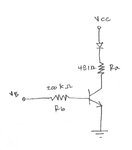
I used 2 100Ω resistance for driving ... Thinking that smaller current will drive bjt (2n2222) into saturation much quickly....


Was i wrong because the schematic worked but the intensity of led which was switched on and off through (89s51) was not maximum....

Was i wrong.....and should i increase the base resistance....:???:

---------- Post added at 10:03 ---------- Previous post was at 10:02 ----------

My basic electronics remind me v/r =i so i thought to minimise the resistance....
 

Did you use the 2x100Ω resistors in the base or in the collector circuit? If it's at the base, what's the collector resistor? If at the collector, what's the base resistor? Are the two 100Ω resistors in series or in parallel?
 

Can you give more info on what you did?
Are you still driving a relay?
Is the LED in the collector path or to determine if the 89s51 output is on?
Is that parallel or series resistors?

Given the information described, I can only guess that you put the led at the base of the transistor to see if the output of uP is high.
And you used either 50 or 200 ohm as the base resistance.
If this is the case, the LED will not turn on because the Vbe of the transistor will clamp the base voltage at 0.7V since the emitter is connected to ground.
The LED needs about 1.6V to turn on. So even though the LED is very dim, the circuit still works.
If this is was you did, then you should have connected the LED before the base resistors to the output of the uP with its own series resistor to limit the current through the LED. Plus, there is really no need to drive the base of the transistor with 50 or 200 ohms. If you use to small a resistance then you will **** to much current out of the uP and it will either burn or lower the output.
 

Status
Not open for further replies.

Part and Inventory Search

Welcome to EDABoard.com

Sponsor

Back
Top