Welcome to our site! EDAboard.com is an international Electronics Discussion Forum focused on EDA software, circuits, schematics, books, theory, papers, asic, pld, 8051, DSP, Network, RF, Analog Design, PCB, Service Manuals... and a whole lot more! To participate you need to register. Registration is free. Click here to register now.
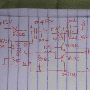
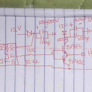
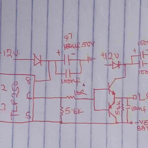
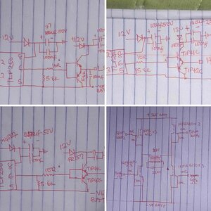
with dummy resistive load i have output 21Vrms @ 36VDC but with transformer connected i have 0vac, regulatior TL783c regulates my 36V to about 22v @700ma then to casacded booster(TIP41C,42C) then to 7812 (12v regulator ) then to (7805) 5v regulator for arduino
my current boost transistor for my...
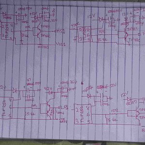
I have removed the capacitor n still get low voltage at my highside driver outputs. Could u redraw my schematics may b my connection of the high side is wrong but low side seems OK . highside is at spwm frequency of 16kHz,low side is at 50Hz
Could it b an error in my connection of the high side because my low side seems ok with 10.4-11.2vat low side but at high side í still get a low voltage 6.7Vac to 7.8Vac . I am using veroboard to test could u show me the connection by redrawing the schematic please!
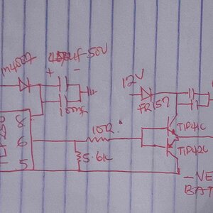
My pwm frequency is 16kHz. I have removed the second driver using tip 41&42 transistors but yet I still get 6.8-7.8VAC at my high side outputs but at my low sides I get BTW 10.4-11.2VAC which seems OK . by the way I am prototyping on veroboard .
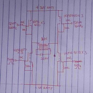
Irfb4110 has gate charge of 210nC max and rise time of 67nS shouldn't my gate current be 210/67 = 3.13A. And my tlp250 can only source .5A and sink 1.5A .
This site uses cookies to help personalise content, tailor your experience and to keep you logged in if you register.
By continuing to use this site, you are consenting to our use of cookies.