/************************************************************
To display temperature (0-99) on two common cathode seven segment displays using multiplexing. Pin a,b,c,d,e,f,g and dp of each seven segment display are connected to PORTB pin 0 to pin 7 through
330 Ohm Resistors.
2 pins of PORTC (RC4 & RC5) are connected to the base of two BC548B Transistors respectively through 1K Resistors. Collectors of each Transistor is connected to common pins of each Seven Segment Display. All the emitters are connected to ground.
I use the circuit to display weather temperature which never goes to 3 digits in Celsius scale. That's why I used 2 Seven Segment Displays. You can use the third display as shown in the display connection schematic.
Vref+ is connected to 5V+ supply and Vref- is connected to 0V which gives enough resolution for my need. You can change if you need. Also read Mr. Tahmid 's blogs on ADC. They are really good.
Processor: pic16F876A with 20MHz Xtal Compiler:MPLAB X8 on MPLAB XIDE v1.95
LM35 output pin is connected to AN0 (pin 2 of 16F876A). For display you can get idea from : https://www.edaboard.com/blog371886-attachment66886d1326004489-sch.png
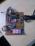
Hera is a picture of the finished model using the above code. Though there are 3 seven segment display modules present on the hardware, the third is not connected. Only 2 are used.

To display temperature (0-99) on two common cathode seven segment displays using multiplexing. Pin a,b,c,d,e,f,g and dp of each seven segment display are connected to PORTB pin 0 to pin 7 through
330 Ohm Resistors.
2 pins of PORTC (RC4 & RC5) are connected to the base of two BC548B Transistors respectively through 1K Resistors. Collectors of each Transistor is connected to common pins of each Seven Segment Display. All the emitters are connected to ground.
I use the circuit to display weather temperature which never goes to 3 digits in Celsius scale. That's why I used 2 Seven Segment Displays. You can use the third display as shown in the display connection schematic.
Vref+ is connected to 5V+ supply and Vref- is connected to 0V which gives enough resolution for my need. You can change if you need. Also read Mr. Tahmid 's blogs on ADC. They are really good.
Processor: pic16F876A with 20MHz Xtal Compiler:MPLAB X8 on MPLAB XIDE v1.95
Code C - [expand]
LM35 output pin is connected to AN0 (pin 2 of 16F876A). For display you can get idea from : https://www.edaboard.com/blog371886-attachment66886d1326004489-sch.png
Hera is a picture of the finished model using the above code. Though there are 3 seven segment display modules present on the hardware, the third is not connected. Only 2 are used.
