SONY SIRC Protocol:
There are three types of SIRC protocol, 12, 15, and 20bit types. All these types have a command and device word. The 20-bit version has only 8bit extended words. Within the bitstream, each word is sent LSB first like this pattern below:
The frame timing is based on multiples of a 600µS pulse with width T. Frames begin with a 4T start mark pulse. Each bit in the frame is represented by a 1T space followed by either a 1T mark (if the bit is 0) or a 2T mark (if the bit is 1). The frame timing is given below:

This pattern is repeated at an interval of 45ms. When a button is pressed in SONY remote, it repeat each frame at-least 3 times.
Modulation:
We have seen the protocol pattern and timing frame. But this signal can not be transmitted so far without modulation. That is why all the IR remotes use modulation in around 36KH ~ 40KHz. SONY SIRC is modulated around 38~40KHz.Modulation is a mix of one carrier signal and a data signal like this:

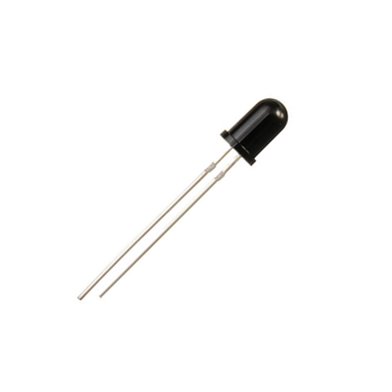
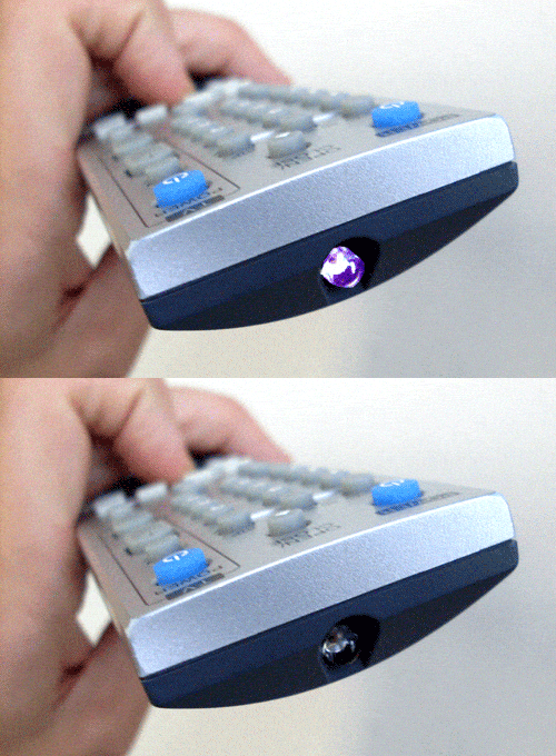
SONY SIRC uses a 38~40KHz carrier signal and then the data according the the pattern of this protocol is combined with this carrier signal. A IR LED works as the transmitter.

In this way the command and address is sent through the IR transmitter (IR LED). As modulation is used, a single battery can last long time and long distance can be achieved.
Example commands:
The table below shows the commands and address of different SONY SIRC temores:| Device | Address | Function | Command |
| TV | 1 | Digit 0 | 9 |
| VCR1 | 2 | Digit 1 | 0 |
| VCR2 | 3 | Digit 2 | 1 |
| LASER Disk | 6 | Digit 3 | 2 |
| Surround Sound | 12 | Digit 4 | 3 |
| Cassette/Tuner | 16 | Digit 5 | 4 |
| CD Player | 17 | Digit 6 | 5 |
| Equalizer | 18 | Digit 7 | 6 |
| Digit 8 | 7 | ||
| Digit 9 | 8 | ||
| Channel + | 16 | ||
| Channel – | 17 | ||
| Volume + | 18 | ||
| Volume – | 19 | ||
| Mute | 20 | ||
| Power | 21 | ||
| Reset | 22 | ||
| Audio Mode | 23 | ||
| Contrast + | 24 | ||
| Contrast – | 25 | ||
| Color + | 26 | ||
| Color – | 27 | ||
| Brightness + | 30 | ||
| Brightness – | 31 | ||
| Balance Left | 38 | ||
| Balance Right | 39 | ||
| Standby | 47 |
Decoding:
The transmitted IR signal is received by a remote sensor. This sensor has built in IR detector and hysteresis comparator. As a result the transmitted modulated signal is received as like the SIRC pattern.

IR Receiver IC1
IR Diode
IR Receiver IC2
Both the IR diode and IR receiver IC can sense the IR signal. But difference is, the IR Diode can not decode the pattern from the received signal. And each IR receiver IC has a built in IR diode inside along with a hysteresis comparator.
The TSOP4838 IR receiver IC is active low type and we need to use a pull up resistor with the output pin.

As the output is active low so the output is inverted. To decode the pattern, a start signal is sensed at first.

Then rest of the signals is decoded.
Flow chart

In the next article, we will make a circuit to decode the SONY SIRC Protocol and will make a device that can be operated remotely with a SONY remote. Today, this article ends here.
I hope this article will be informative to you and you can make your own decoder now. Thanks for reading.
Full article here: https://labprojectsbd.com/2021/03/17/sony-sirc-protocol-decoding/

