The OK7110-C's screen timing requires the dedicated calculation tool starFive_DSI_Tool.exe, which is stored in the Tools/dsi_tool folder of the user profile.
hactive: Effective screen length
Vactive:Effective screen width
Bpp:bit per pixel Pixel depth
fps:frame per second Frame rate
pixelclock_source:Pixel clock source. Because pixel clock is divided by JH7110 PLL2 integer frequency, here need to input PLL2 frequency; VF2 is 1188MHz.
dlanes: mipi dsi Number of channels
ref_pixclk:reference pixel clock reference pixel clock; according to the screen datasheet to know its reference pixel clock or reference pixel clock range.If it is a range, it is better to write the low bound here; this parameter can be filled with 0 to indicate that the reference clock is not used in the calculation or needs to calculate the timing of other frame rates.
nr_timing_generated:Number of time series to be generated
For example


Run the script run. Sh.
Use the command./run. Sh.

Use the command./run. Sh. The timing generated by the tool is calculated from input.ini.
For example:
The number of generated timings is determined by the nr_timing_generated parameter in input.ini.
Note that if output.txt is generated in multiple groups,not every group will work properly. It is necessary to try them one by one to select the right timing for the screen.
Timing example:
Make changes against the device tree file OK7110-C.dts:
1. Modify the seeed_plane point:
dlanes: Modify according to the number of channels used on the screen.
width-mm,height-mm,data-mapping:Modify according to the actual information on the screen.
2. Modify mipi_dsi node:
Bitrate,hsa,hbp,hfp;modify according to the corresponding values in generation_timing.dsi_timing
3. panel-timing: The data in panel-timing, hactive and vactive are filled in according to the actual value of the screen; the rest of the panel-timing is modified according to the corresponding content in the generation sequence.dpi_timing. panel-timing. The modifications are as follows:
After the modification, burn the new device tree into the device and see if it can be displayed properly.
If it can't be displayed normally, use the rest of the timings in output.txt and continue to try according to the above steps; if it can be displayed normally, the screen adaptation is completed.
Originally published at www.forlinx.net.
Operation methods:
01 Parameter configuration
Modify the input.ini file, which is used to configure the screen parameters; the following are the specific configuration parameters:hactive: Effective screen length
Vactive:Effective screen width
Bpp:bit per pixel Pixel depth
fps:frame per second Frame rate
pixelclock_source:Pixel clock source. Because pixel clock is divided by JH7110 PLL2 integer frequency, here need to input PLL2 frequency; VF2 is 1188MHz.
dlanes: mipi dsi Number of channels
ref_pixclk:reference pixel clock reference pixel clock; according to the screen datasheet to know its reference pixel clock or reference pixel clock range.If it is a range, it is better to write the low bound here; this parameter can be filled with 0 to indicate that the reference clock is not used in the calculation or needs to calculate the timing of other frame rates.
nr_timing_generated:Number of time series to be generated
For example
02 Running
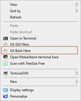
You need to install git on Windows.Open the DSI _ tool directory with git bashRun the script run. Sh.
Use the command./run. Sh.
Use the command./run. Sh. The timing generated by the tool is calculated from input.ini.
For example:
The number of generated timings is determined by the nr_timing_generated parameter in input.ini.
Note that if output.txt is generated in multiple groups,not every group will work properly. It is necessary to try them one by one to select the right timing for the screen.
Timing example:
Make changes against the device tree file OK7110-C.dts:
1. Modify the seeed_plane point:
dlanes: Modify according to the number of channels used on the screen.
width-mm,height-mm,data-mapping:Modify according to the actual information on the screen.
2. Modify mipi_dsi node:
Bitrate,hsa,hbp,hfp;modify according to the corresponding values in generation_timing.dsi_timing
3. panel-timing: The data in panel-timing, hactive and vactive are filled in according to the actual value of the screen; the rest of the panel-timing is modified according to the corresponding content in the generation sequence.dpi_timing. panel-timing. The modifications are as follows:
After the modification, burn the new device tree into the device and see if it can be displayed properly.
If it can't be displayed normally, use the rest of the timings in output.txt and continue to try according to the above steps; if it can be displayed normally, the screen adaptation is completed.
Originally published at www.forlinx.net.