Here I will show you how to use the compare section of the CCP (Compare, Capture, Pulse Width Modulation) module of the PIC16F877A. You can use this concept for any PIC with a CCP/ECCP module.
There are 2 modules associated with the compare section – the CCP module which we’ll use for the compare function, and the Timer 1 module. The function of the compare module is to compare (obviously, as the name suggests) the value of the CCPR1 register against the Timer 1 value. The CCPR1 register is actually composed of two 8-bit registers that together form a 16-bit register. The high 8-bits – the high byte – make up the CCPR1H register and the low 8-bits – the low byte – make up the CCPR1L register.
For example, if the value of CCPR1H is 30 and the value of CCPR1L is 47, what is the value of the 16-bit CCPR1 register?
Solution:
CCPR1H = 30 = 0x1E
CCPR1L = 47 = 0x2F
So, the high byte = 0x1E. The low byte = 0x2F.
CCPR1 = 0x1E2F = 7727
Like CCPR1, TMR1 is a 16-bit register composed of two 8-bit registers – TMR1H and TMR1L. If TMR1H = 30 and TMR1L = 47, TMR1 = 7727.
Back to the function of the compare mode. The 16-bit value of CCPR1 is compared against the 16-bit value of TMR1. RC2 pin is associated with the CCP module. Upon match of the CCPR1 register against TMR1 (when CCPR1 is equal to TMR1), one of the following can happen to RC2 (RC2 is the pin associated with the CCP module) depending on the setting of the CCP1CON register:
• RC2 is driven high
• RC2 is driven low
• RC2 is unaffected
If RC2 is to be used, TRISC2 must be cleared to make RC2 a digital output.
Upon match of CCPR1 and TMR1 (when CCPR1 is equal to TMR1), CCP1IF (bit 2 of PIR1) is set. If the CCP interrupt is enabled, a CCP interrupt is generated. To enable the CCP interrupt, CCP1IE (bit 2 of PIE1) has to be set.
Another interesting setting of the CCP module is that it can be set up so that upon compare match of CCPR1 and TMR1, the following happen:
• CCP1IF is set
• CCP interrupt is generated if CCP1IE is set
• RC2 is unaffected
• Timer 1 is reset (TMR1 = 0)
• If the ADC module is enabled, an A/D conversion is started
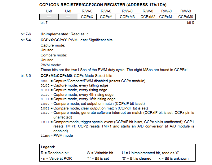
What happens when there is a compare match of CCPR1 and TMR1 depends on the setting of the CCP1CON register. Here is the CCP1CON register:

• When CCP1CON = 8 (0x08), CCP1 module is configured for compare mode and is set up so that upon a compare match of CCPR1 and TMR1, RC2 is driven high.
• When CCP1CON = 9 (0x09), CCP1 module is configured for compare mode and is set up so that upon a compare match of CCPR1 and TMR1, RC2 is driven low.
• When CCP1CON = 10 (0x0A), CCP1 module is configured for compare mode and is set up so that upon a compare match of CCPR1 and TMR1, RC2 is unaffected.
• When CCP1CON = 11 (0x0B), CCP1 module is configured for compare mode and is set up so that upon a compare match of CCPR1 and TMR1, RC2 is unaffected, TMR1 is reset and an A/D conversion is started if the ADC module is enabled.
Remember that in all compare modes, whenever there is a compare match of CCPR1 and TMR1, CCP1IF is set.
Now let’s take a look at a code example to make things clear. Let’s say we’re running a PIC16F877A with a crystal oscillator of frequency 20MHz. Let’s use the compare mode to generate a 50Hz output with 50% duty cycle.
Solution:
Tcy = (1/20000000)*4*106 us = 0.2us
Since one TMR1 increment takes 1 instruction cycle (with prescaler 1:1), one TMR1 overflow takes 65536 instruction cycles. That’s 65536 * 0.2us = 13107.2us = 13.1072ms. For 50Hz, time period = 20ms. So with 50% duty cycle, on time is 10ms.
The number of instruction cycles in 10ms is equal to (10000/0.2) = 50000.
When TMR1 = 50000 after counting up from 0, 10ms will have elapsed. So, we’ll assign 50000 to CCPR1 so that a compare match occurs every 10ms. We’ll use the CCP setting for trigger special event where TMR1 is reset upon compare match.
CCPR1 = 50000 = 0xC350
Therefore, CCPR1H = 0xC3 and CCPR1L = 0x50
For our required mode of operation, CCP1CON = 11. As CCP interrupt will be used, CCP1IE must be set. GIE and PEIE also have to be set.
We’ll use RC0 as our output pin. Every 10ms, the state of RC0 must be toggled. We’ll do the toggling in the interrupt service routine (ISR). We chose to use RC0. Since in our mode of operation, RC2 is unaffected, we can use any pin really and I arbitrarily chose to use RC0. If any of the pins that are multiplexed to the ADC module or the comparator module is to be used, remember to disable the analog circuitry and use that pin as digital output.
The code should be quite easy to understand. Here it is:
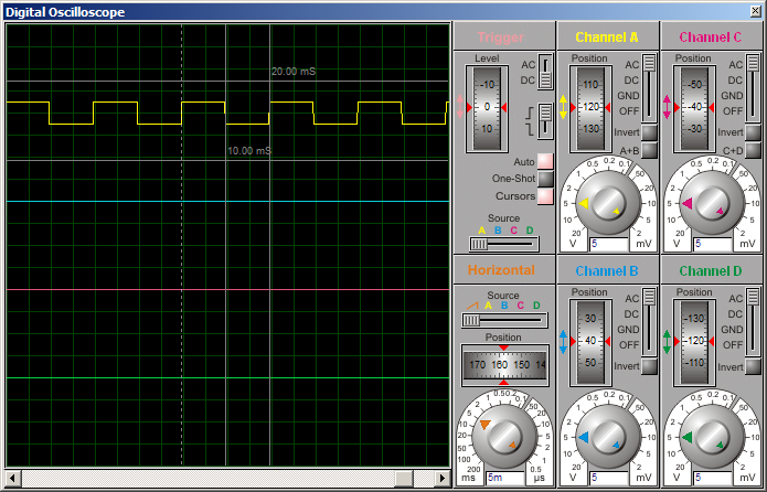
Here is the output waveform:

Now let’s take a look at another code example. Let’s say we’re running a PIC16F877A with a crystal oscillator of frequency 20MHz. Let’s use the compare mode to generate a 50Hz output with 75% duty cycle.
Solution:
Tcy = 0.2us
In the previous example, as duty cycle was 50%, the simple thing to do was to toggle the output pin. Here we cannot do that as duty cycle is 75%.
This time, we’ll use RC2 as the output pin.
Time period = 20ms. With 75% duty cycle, on time is 15ms. Off time is 5ms.
Number of instruction cycles for 5ms = (5000/0.2) = 25000. Number of instruction cycles for 15ms = 75000. This is beyond the maximum for TMR1. So, we’ll utilize the TMR1 prescaler. We’ll use a prescaler 1:2.
So, for 5ms, number of TMR1 increments = 12500. For 15ms, number of TMR1 increments = 37500.
We’ll change the CCP1CON setting from 8 to 9 to 8 to set the output high to low to high upon consecutive compare matches. We’ll need to alternately change CCPR1 between 12500 and 37500 as required.
12500 = 0x30D4
37500 = 0x927C
In the 2 modes of operation we chose to use, TMR1 is not cleared/reset upon compare match. So, in the interrupt, we must clear TMR1 manually to start TMR1 counting from 0.
If you understand how this code works, you should be clear about the compare module by now.
Here is the code:
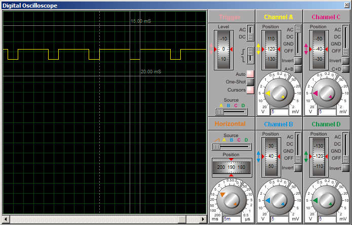
Here is the output waveform:

The compare section of the CCP module is very useful for timing-dependent applications. As shown above, you can use it for PWM at frequencies that are too low for the PWM section of the CCP module.
If clearly understood, it is very easy to use and I hope I could make the compare mode of the CCP module clear. Your comments and feedback are welcome.
There are 2 modules associated with the compare section – the CCP module which we’ll use for the compare function, and the Timer 1 module. The function of the compare module is to compare (obviously, as the name suggests) the value of the CCPR1 register against the Timer 1 value. The CCPR1 register is actually composed of two 8-bit registers that together form a 16-bit register. The high 8-bits – the high byte – make up the CCPR1H register and the low 8-bits – the low byte – make up the CCPR1L register.
For example, if the value of CCPR1H is 30 and the value of CCPR1L is 47, what is the value of the 16-bit CCPR1 register?
Solution:
CCPR1H = 30 = 0x1E
CCPR1L = 47 = 0x2F
So, the high byte = 0x1E. The low byte = 0x2F.
CCPR1 = 0x1E2F = 7727
Like CCPR1, TMR1 is a 16-bit register composed of two 8-bit registers – TMR1H and TMR1L. If TMR1H = 30 and TMR1L = 47, TMR1 = 7727.
Back to the function of the compare mode. The 16-bit value of CCPR1 is compared against the 16-bit value of TMR1. RC2 pin is associated with the CCP module. Upon match of the CCPR1 register against TMR1 (when CCPR1 is equal to TMR1), one of the following can happen to RC2 (RC2 is the pin associated with the CCP module) depending on the setting of the CCP1CON register:
• RC2 is driven high
• RC2 is driven low
• RC2 is unaffected
If RC2 is to be used, TRISC2 must be cleared to make RC2 a digital output.
Upon match of CCPR1 and TMR1 (when CCPR1 is equal to TMR1), CCP1IF (bit 2 of PIR1) is set. If the CCP interrupt is enabled, a CCP interrupt is generated. To enable the CCP interrupt, CCP1IE (bit 2 of PIE1) has to be set.
Another interesting setting of the CCP module is that it can be set up so that upon compare match of CCPR1 and TMR1, the following happen:
• CCP1IF is set
• CCP interrupt is generated if CCP1IE is set
• RC2 is unaffected
• Timer 1 is reset (TMR1 = 0)
• If the ADC module is enabled, an A/D conversion is started
What happens when there is a compare match of CCPR1 and TMR1 depends on the setting of the CCP1CON register. Here is the CCP1CON register:

• When CCP1CON = 8 (0x08), CCP1 module is configured for compare mode and is set up so that upon a compare match of CCPR1 and TMR1, RC2 is driven high.
• When CCP1CON = 9 (0x09), CCP1 module is configured for compare mode and is set up so that upon a compare match of CCPR1 and TMR1, RC2 is driven low.
• When CCP1CON = 10 (0x0A), CCP1 module is configured for compare mode and is set up so that upon a compare match of CCPR1 and TMR1, RC2 is unaffected.
• When CCP1CON = 11 (0x0B), CCP1 module is configured for compare mode and is set up so that upon a compare match of CCPR1 and TMR1, RC2 is unaffected, TMR1 is reset and an A/D conversion is started if the ADC module is enabled.
Remember that in all compare modes, whenever there is a compare match of CCPR1 and TMR1, CCP1IF is set.
Now let’s take a look at a code example to make things clear. Let’s say we’re running a PIC16F877A with a crystal oscillator of frequency 20MHz. Let’s use the compare mode to generate a 50Hz output with 50% duty cycle.
Solution:
Tcy = (1/20000000)*4*106 us = 0.2us
Since one TMR1 increment takes 1 instruction cycle (with prescaler 1:1), one TMR1 overflow takes 65536 instruction cycles. That’s 65536 * 0.2us = 13107.2us = 13.1072ms. For 50Hz, time period = 20ms. So with 50% duty cycle, on time is 10ms.
The number of instruction cycles in 10ms is equal to (10000/0.2) = 50000.
When TMR1 = 50000 after counting up from 0, 10ms will have elapsed. So, we’ll assign 50000 to CCPR1 so that a compare match occurs every 10ms. We’ll use the CCP setting for trigger special event where TMR1 is reset upon compare match.
CCPR1 = 50000 = 0xC350
Therefore, CCPR1H = 0xC3 and CCPR1L = 0x50
For our required mode of operation, CCP1CON = 11. As CCP interrupt will be used, CCP1IE must be set. GIE and PEIE also have to be set.
We’ll use RC0 as our output pin. Every 10ms, the state of RC0 must be toggled. We’ll do the toggling in the interrupt service routine (ISR). We chose to use RC0. Since in our mode of operation, RC2 is unaffected, we can use any pin really and I arbitrarily chose to use RC0. If any of the pins that are multiplexed to the ADC module or the comparator module is to be used, remember to disable the analog circuitry and use that pin as digital output.
The code should be quite easy to understand. Here it is:
Code:
//Programmer: Syed Tahmid Mahbub
//Target Microcontroller: PIC16F877A
//Compiler: mikroC PRO for PIC
//Using Compare Section of PIC CCP Module - using PIC16F877A

void interrupt(){
     if (CCP1IF_bit == 1){
        RC0_bit = ~ RC0_bit; //Toggle RC0
        CCP1IF_bit = 0;
     }
}

void main() {
     PORTC = 0;
     TRISC = 0;
     CCP1CON = 11;
     CCP1IE_bit = 1;
     GIE_bit = 1;
     PEIE_bit = 1;
     CCPR1H = 0xC3;
     CCPR1L = 0x50;
     //CCPR1 = 0xC350 = 50000
     T1CON = 0x01; //Prescaler 1:1, start Timer 1
     while(1){
     //Do whatever else is required
     }
}
Here is the output waveform:

Now let’s take a look at another code example. Let’s say we’re running a PIC16F877A with a crystal oscillator of frequency 20MHz. Let’s use the compare mode to generate a 50Hz output with 75% duty cycle.
Solution:
Tcy = 0.2us
In the previous example, as duty cycle was 50%, the simple thing to do was to toggle the output pin. Here we cannot do that as duty cycle is 75%.
This time, we’ll use RC2 as the output pin.
Time period = 20ms. With 75% duty cycle, on time is 15ms. Off time is 5ms.
Number of instruction cycles for 5ms = (5000/0.2) = 25000. Number of instruction cycles for 15ms = 75000. This is beyond the maximum for TMR1. So, we’ll utilize the TMR1 prescaler. We’ll use a prescaler 1:2.
So, for 5ms, number of TMR1 increments = 12500. For 15ms, number of TMR1 increments = 37500.
We’ll change the CCP1CON setting from 8 to 9 to 8 to set the output high to low to high upon consecutive compare matches. We’ll need to alternately change CCPR1 between 12500 and 37500 as required.
12500 = 0x30D4
37500 = 0x927C
In the 2 modes of operation we chose to use, TMR1 is not cleared/reset upon compare match. So, in the interrupt, we must clear TMR1 manually to start TMR1 counting from 0.
If you understand how this code works, you should be clear about the compare module by now.
Here is the code:
Code:
//Programmer: Syed Tahmid Mahbub
//Target Microcontroller: PIC16F877A
//Compiler: mikroC PRO for PIC
//Using Compare Section of PIC CCP Module - using PIC16F877Avoid interrupt(){
     if (CCP1IF_bit == 1){
        TMR1H = 0;
        TMR1L = 0;
        //TMR1 must be cleared manually
        if (CCP1CON == 8){
           CCP1CON = 9;
           CCPR1H = 0x92;
           CCPR1L = 0x7C;
           //CCPR1 = 37500 --> 15ms
        }
        else{
             CCP1CON = 8;
             CCPR1H = 0x30;
             CCPR1L = 0xD4;
             //CCPR1 = 12500 --> 5ms
        }
        CCP1IF_bit = 0;
     }
}

void main() {
     TRISC = 0;
     PORTC = 4;
     CCP1CON = 9; //Clear RC2 on match
     CCPR1H = 0x92;
     CCPR1L = 0x7C;
     //CCPR1 = 37500 --> 15ms
     CCP1IE_bit = 1;
     GIE_bit = 1;
     PEIE_bit = 1;
     T1CON = 0x11; //Prescaler 1:2, start Timer 1
     while(1){
     //Do whatever else is required
     }
}
Here is the output waveform:

The compare section of the CCP module is very useful for timing-dependent applications. As shown above, you can use it for PWM at frequencies that are too low for the PWM section of the CCP module.
If clearly understood, it is very easy to use and I hope I could make the compare mode of the CCP module clear. Your comments and feedback are welcome.