Continue to Site

Welcome to EDAboard.com

Welcome to our site! EDAboard.com is an international Electronics Discussion Forum focused on EDA software, circuits, schematics, books, theory, papers, asic, pld, 8051, DSP, Network, RF, Analog Design, PCB, Service Manuals... and a whole lot more! To participate you need to register. Registration is free. Click here to register now.

Frequency Doubler circuit

Status
Not open for further replies.

Ashish.chip

Newbie level 6
Newbie level 6
Joined
Feb 12, 2007
Messages
14
Helped
0
Reputation
0
Reaction score
0
Trophy points
1,281
Visit site
Activity points
1,392
frequency doubler circuit

I want a frequency doubler circuit so that i can double frequency of a given Square wave input.I want to solve this problem only in analog.so plzz suggest me a circuit for this....
thanks a lot!!!
 

frequency doubler schematic

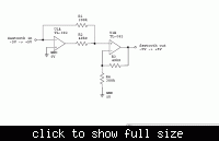
If you can convert the square signal to sawtooth, this is the schematic:
**broken link removed**
 

frequency doubler

You can try using PLL with division ratio of 2 .Or you can use a harmonic generator of a non-linear element to generate second harmonic sin wave then convert it into a square wave but I recommend the PLL method .
 

xor frequency doubler

I think one way to double frequency is to use source coupled differential pair - If you apply differential clocks to source coupled pair, then the frequency of signal at the source will be twice of input frequency - but maybe need amplifier(comparator) to amplify it
 

frequency doubler circuits gates

What the hell people don't know how to ask ?
And why the people are answering to incomplete questions ?
:)

To understand the stupidity of this question imagine the frequency which must be doubled is:

a. 1Khz
b. 5Ghz

Now do you understand what did I mean ?
Those two frequencies multiplication need a totally different approach.
 

1 chip xor frequency doubler

using counters no other way
 

frequency doubler ic

hung_wai_ming(at)hotmail.com said:
Hi bageduke,

Why source coupled pair can generate double frequency ?


Well, we normally deal the common source of source coupled pair as virtual ground, but it actually goes up and down with input voltage. The frequency of it is double of input frequency. You can refer to razavi's book - if I didn't mis-remember it.
 

low frequency multiplier circuits

if you don't care duty cycle .. you can use
edge trigh(like D_ff ) + XOR cell

rise/fall edge generate 2 pulse ..
and add some delay cell
let width more wide
 

pulse frequency doubler

Hi ALL

I once designed frequency doubler in logic gates but use calibration to obtain precise 50-50 duty cycle. However the calibration logic took me quite a number of gate counts, so I would like to sort for some other ways to do it in either analog or simple logic which can also generate 50-50 duty cycle. My target input frequency is 20MHz.

Hi melc,
Please disclose your so-called "method" to let us know. Thanks

Added after 1 minutes:

Hi IBO

we are talking about frequency doubler, not frequency divider
 

frequency doubler schottky diodes

Hi All,

Let me mention another method for a frequency doubler circuit, apparently neglected by many people, which is a four quadrant multiplier or known as Gilbert cell. If you connect the two inputs together and apply a sinusoidal input, you will get a DC term + a double frequency sinusiodal voltage at the output. It is nearly as wide band doubler as the multiplier circuit itself, with low distortion.
Typical multiplier circuits in IC form have been ua796 or MC1495 of past era, now you may find newer names from Analog Devices for instance or Harris etc.

See an application on a wideband frequency doubler with a multiplier of an Analoge Devices AD834JN, page 7-8 in Data Sheet:
http://www.datasheetcatalog.com/datasheets_pdf/A/D/8/3/AD834JN.shtml

Search for different types to fit your needs (http://www.chipsinfo.com/Cat/80.htm)

Another possibilty is using the well known full wave rectifier because there is a double frequency at its output: if you rectify a 50 or 60Hz AC voltage, the ripple voltage is at 100 or at 120Hz at the output of a full wave rectifier (do not use a puffer capacitor to see the series of half sine waves). Of course this output needs further filtering at the double frequency to clean the signal at the output and get rid of the DC term. So this solution, though works up to the GHz range, is mainly limited to one practical input frequency range/value because of the output filter bandwidth. See link for a basic full wave rectifier what I mean:

**broken link removed** and see the center tapped transformer with the two diode in the Full Wave Rectifiers part of the page.
By using matched Schottky diodes and wide band transmission line transformers "this doubler" is really wideband. A band pass filter is needed at the output for making a sinusoidal voltage at the double frequency.

For low frequency use this active rectifier:
**broken link removed** and also a filter is needed at the output.

Regards
unkarc
 

frequency doubler integrator xor capacitor

Just to add another option.

If your input is sinusoidal, or if you can filter your input so that you get a waveform that is near a sinus you can then just use a 2 (or 4) diodes full wave rectifier.
At the output you will get a signal that will have as fundamental frequency the double of the input frequency. Of course there are still higher order harmonics that you will have to filter out......

Another idea. If you have a voltage controlled adjustable delay that can be adjusted to give 90 degrees at the input frequency, then you can make an XOR of the input signal and the signal delayed by 90 degrees. You will get a square wave at the output that will have the fuldamental frequency at the double of the input frequency. If you measure the average DC voltage at the output (using a filter or an integrator) you will be able then to use this DC voltage to control the delay using a negative feedback. In this way you will be able to suppress completely the input frequency from the output signal, i.e., get a perfect squarewave with 50% duty cicle,i.e., no presence of the input frequency......

Hope it helps.
S.
 

digital frequency multiplier circuit

I think for Freq. doubler with 50:50 duty cycle ( or 60:40 at least),

the best way is pll.

for example, u want the output 40MHz, u should make 80MHz VCO output and then divide /2 it for duty cycle.

But, u should make just logic and for duty cycle, it is IMPOSSIBLE because of P.V.T variation.

If u cant use pll..

the 2nd way is replica-VCDL.

This is not affected supply, but add strong bias block for temp. & process variation.

If u want the behavior just input - output as soon as possible, choice 2nd way,

and dont concern the lock time ( input - output time ), choice 1nd way.

eyes146@hotmail.com
 

Hi
This link:
**broken link removed**

is filtered in my country. Would you please download it for me?
 

this was a question in last years final exam
check out the circuit in the first question. It was used in the Pentium 4 design.
My college professor was actually a design engineer at Intel for 5 years
 

Attachments

  • FinalFall2009_594BB.pdf
    3.1 MB · Views: 330

You can double a frequency by feeding the input signal into both inputs of a double balanced mixer.

Keith

---------- Post added at 10:19 ---------- Previous post was at 10:16 ----------

Oops - I think that has already been mentioned.
 

There are a number of ways. Lets say it is a 50% duty cylcle square wave at a frequency of 10 MHz. A square wave has odd harmonics.

1) it is easy to produce 30 or 50 MHz from the squarewave using only analog means. You would simply make either a 30 or 50 mhz bandpass filter, it would pass only the energy you desire, then you could use a transistor amplifier to reamplify the signal to make it useable. But since only odd harmonics are present, you are not going to get much 20 MHz.

2) You could lowpass filter the 10 MHz squarewave to turn it into a sine wave. You then would amplify it, input it into a transformer primary. At the secondary, you would ground the center tap, and use a series shottky diode on the + lead, and a reverse series diode on the -lead. You combine the two diodes together and you would get a fullwave rectifier, or "push-push" type of output that would have strong 20 MHz, and have the 10 Mhz somewhat suppressed.

3) using digital means, you can do some things with XOR gates and short lengths of coaxial delay line to take a single pulse and turn it into 2 pulses--which would look like twice the frequency. But that would be cheating because it uses digital circuits.

4) you could have an analog 20 MHz voltage controlled oscillator. You would sample its output with a diode sampler circuit at a 10 MHz rate. You would take that sampled output, filter it with some R-C components, and drive the tuning port on the oscillator. A sampler made from diodes is considered an "analog" circuit, so you would be legal.

5) you could drive the square wave into some highly non-linear device, like a saturated ferrite or a voltage controlled capacitor (varctor diode). As it charged the reactive device, the non-linearity would cause currents to flow at 10, 20, 30....MHz. You would filter off the 20 Mhz, and reamplifiy it.

6) you could drive the 10 MHz square wave into a length of transmission line. Along the length of the transmission line you could place some high impedance voltage sampling taps. The first tap goes to a + on a summing junciton op amp, 2nd tap goes to - on summing junciton, 3rd tap goes to + on summing junciton, 4th goes on - summing junction. End of transmission line is terminated in the line's characteristic impedance for no reflections. As the pulse travels by first tap op amp goes high, after pulse travels by 2nd tap op amp goes to zero, as pulse travels by 3rd tap op amp output goes high, etc. Need to space taps by the right time delay.


7) you could have some electromechanical mechanism that was tuned to 20 Mhz (like a crystal resonator, or a MEMS cantilevered arm, etc) and you could capacitively coulple the 10 MHz square wave into it. The spike from the leading edge of the 10 MHz square wave would inject energy into the resonant circuit, where it would "ring" at a 20 mhz rate. For that matter, you could probably just have an L-C resonator that you capacitively feed with spikes from the square wave input, and it would ring out at the 20 MHz rate.
Probably another 20 more ways if you think hard enough.
 
Last edited:

Status
Not open for further replies.

Part and Inventory Search

Welcome to EDABoard.com

Sponsor

Back
Top