paragon
Newbie level 1

pspice flipflop
Hello All,
I am new to this forum as well as Orcad.
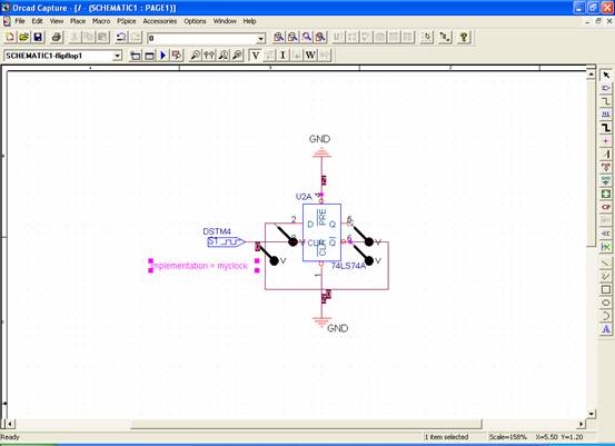
I having some problems simulating a Flip-Flop ( 74LS74 from the psice lib)
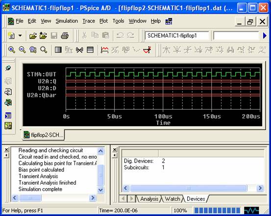
When running the simulation I can see the alternating digital output from dstm into the clk of the flip-flop but when monitoring the D Q and QBar of the flip-flop all I see is three red flat lines ie no digital output.
If anyone could help explain how to implement this or even point me to a good tutorial / guide that would be great as I have googled this to death ;-)
I have purchased some books for Orcad from Amazon but am awaiting delivery.
I have uploaded two images, one of the capture and the other of the ocilloscope (pspice simulation)


TIA
SRG
Hello All,
I am new to this forum as well as Orcad.
I having some problems simulating a Flip-Flop ( 74LS74 from the psice lib)
When running the simulation I can see the alternating digital output from dstm into the clk of the flip-flop but when monitoring the D Q and QBar of the flip-flop all I see is three red flat lines ie no digital output.
If anyone could help explain how to implement this or even point me to a good tutorial / guide that would be great as I have googled this to death ;-)
I have purchased some books for Orcad from Amazon but am awaiting delivery.
I have uploaded two images, one of the capture and the other of the ocilloscope (pspice simulation)


TIA
SRG


