Continue to Site

Welcome to EDAboard.com

Welcome to our site! EDAboard.com is an international Electronics Discussion Forum focused on EDA software, circuits, schematics, books, theory, papers, asic, pld, 8051, DSP, Network, RF, Analog Design, PCB, Service Manuals... and a whole lot more! To participate you need to register. Registration is free. Click here to register now.

Corner analysis & Process variation?

Status
Not open for further replies.

evilguy

Full Member level 4
Full Member level 4
Joined
Sep 21, 2005
Messages
206
Helped
21
Reputation
42
Reaction score
8
Trophy points
1,298
world5.monstersgame.co.uk
Activity points
2,768
corner analysis

is process corner show process variation in the process? for example, if we do corner analysis in TSMC 0.18µ process, can we conclude that process variation will occur only in the range of corner analysis? i'm a bit confuse a bout this two term. can someone explain to me what are this to represent.
 

process corner analysis

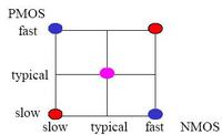
the typical corner is stand for the typical case
the ss corner is stand for slow NMOS and slow PMOS case
the ff corner is fast NMOS and fast PMOS case
the fs corner is fast NMOS and slow PMOS case
the sf corner is slow NMOS and fast PMOS case
as the attached image, we believe the most case is located in this area
 
slow voltage and temperature corner

yeah, corner analysis have to include the process variation, in gerneral, corner analysis is called PVT analysis, that's means process, voltage and temperature are variated, and then consider circuit's function and performance.

Best regards
 
site:www.edaboard.com process corners

if i have nMOS and pMOS BSIM4 spice parameter for typical, fast and slow model. how can i use all these model to simulate my circuit. what to varied in these spice model to mimic the process variation in the simulation?

from what i've known, fab house include the model for process variation, monte carlo model, and corner model in their design kit. how can i use existing typical, fast and slow model that i have obtained to include process variation model in it.

i'm still a bit confuse about process corner and process variation.
 

slow process corner

I am interested in this topic as well. Can somebody answer those questions?

1. How can they generate the typical, fast or slow model for transistor??
2. If I have tons of data (IV curves from different situations), how to generate the monte carlo model or corner model?
3. Is there any books or handbooks talk about the related topic?
 

monte carlo corner spice

any simulatin can be run across corners , i.e. corners are just models for elements like MOSTs , BJTs, resistors ,caps.......etc behaving in a non-typical behaviour so u should be able to run them along any simulation
 

chip corners sss ttt

safwatonline said:
any simulatin can be run across corners , i.e. corners are just models for elements like MOSTs , BJTs, resistors ,caps.......etc behaving in a non-typical behaviour so u should be able to run them along any simulation

Do u mean that I have to run each simulation about 4 times (ff, fs, sf, ss) for every circuit containing PMOS and NMOS? and i have to change models every time? But i think this will be difficult if done manually, i.e. it should have certain way of automation! isn't it???!

Thanks,
Ahmad,
 

corner analysis cmos process

Do u mean that I have to run each simulation about 4 times (ff, fs, sf, ss) for every circuit containing PMOS and NMOS? and i have to change models every time? But i think this will be difficult if done manually, i.e. it should have certain way of automation! isn't it???!

U can use ocean scripts for that. You can specify the process section of the model library as a variable and assign a list that contains all process sections to the variable
 
  • Like
Reactions: Johnynash

    evilguy

    Points: 2
    Helpful Answer Positive Rating

    Johnynash

    Points: 2
    Helpful Answer Positive Rating
no.of corners analyze

yes u have to do an ocean script, note also that there are more than 4 combination taking temp. and supply and corners for resistors and caps. and coils and .... there can be thousands of corners
 
  • Like
Reactions: Johnynash

    evilguy

    Points: 2
    Helpful Answer Positive Rating

    Johnynash

    Points: 2
    Helpful Answer Positive Rating
process corners fast slow

safwatonline said:
yes u have to do an ocean script, note also that there are more than 4 combination taking temp. and supply and corners for resistors and caps. and coils and .... there can be thousands of corners

Hello Safwat :)
Please list all possible combinations of corners..
Also, if u have anything discribing corners concept, so please put it here after.
Or you can put it here:


Thank you ...
Kol 3am wenta be7'eer :D
Ahmad,
 

process corner model

So, if we want to assure our design is robust, how many corner we have to consider? is this corner analysis represent process variation in ic fabrication?
 

hspice pvt process variation

evilguy said:
So, if we want to assure our design is robust, how many corner we have to consider? is this corner analysis represent process variation in ic fabrication?

If you are doing purely digital design you can do the following as minimum number of corners:
TTT
SSS (-20% or process dependent)
FFF (+20% or process dependent)
TFS
TSF

For mixed signal stuff you need to add the I/O nMOS and pMOS to the list so it would look like:
TTTTT
SSSSS
FFFFF
TFSFS
TSFSF
TTTSS
TTTFF

Hope that helps.
 
corner analysis slow fast

i think u have at the end to pass them all, but if u use some intuition u may know what are the most important corners for ur design , which can be like high temp. have highest noise , lowest supply can turn some MOSTs off and so on ,but it is really dependent on the design and some corners might be bad and u don't think they are ,so at the end u must do all the corners to be 100 % sure
 

projects in process variation in ic fabrication

sparso said:
evilguy said:
So, if we want to assure our design is robust, how many corner we have to consider? is this corner analysis represent process variation in ic fabrication?

If you are doing purely digital design you can do the following as minimum number of corners:
TTT
SSS (-20% or process dependent)
FFF (+20% or process dependent)
TFS
TSF

For mixed signal stuff you need to add the I/O nMOS and pMOS to the list so it would look like:
TTTTT
SSSSS
FFFFF
TFSFS
TSFSF
TTTSS
TTTFF

Hope that helps.

what the meaning of those? can you explain further in detail? thank you
 

corner fff and sss

Corner analysis and process variation simulations are important in the design and especially for analog designers.
The question about how many corners you want to simulate is the similar to asking how many Montecarlo runs to do I need to run ( I assume you know what Montecarlo is). The answer to this question is how much confidence you want to have in your circuit, which also means what is the expected yeild that you are shooting for, and at the end of the day, it translates into money.
The more corners you design works at successfully, the higher your confidience in your circuit you will have which means better (higher yeild). This is particulary important for companies who build chips for production as opposed to academia.
For example, if you want to build a chip that is going to be used in cars, you must have higher reliability of your chip, which means it should work under all conditions (may be sever conditions such as Temperature from -40C to 125C). The more corners you run also means more cost because you will spend more time in verification as well as testing.
At the end of the day, you will find the answer of this question will depend on the end market of your chip.
One thing to keep in mind, if you just run your design under the TTTTT corner, and then tapeout your chip, what you will find when the chip comes back that you will throw many chips until you find one is working (or barely working). This might be okay if you just want to prove a concept or idea and you don't want to spend too much time in the verification process.

Hope that helps...
 
umc monte carlo ocean script

thanks analog_guru, it help me. i

've some discussion with my lecturer about process corner. what i understand about corner analysis is what you describe above. the reason we do corner analysis is to make sure our design can work perfectly with the present of process variation. for example, let say when we fabricate our chip, the threshold voltage deviate from nominal value, if we do corner analysis, we might have predicted the impact of threshold voltage variation to our chip and do some modification to compensate threshold voltage variation. so at the end, the chip can work well although the threshold voltage varied.

however, my lecturer said to me fast, slow and typical process in ic fabrication are referring to how the ic is fabricate. for example in fast process, the dopant concentration is different from typical and slow process. the asid use in etching step also might different from one corner to other corner. that is why the electrical properties is different in different process corner.

so which one is true?

So the concussion is, we can select which process either fast, typical or slow process when we want to fabricate our ic? so SPICE model for corner analysis given in the pdk from the foundry doesnt represent process variation, however it represent on what 'mode' our transistor is in either typical, fast, or slow 'mode' due to different type of fabrication 'mode'.

hope someone can clarify that. i dont know which one is true. thank you
 
ic corner ff ss stand for

U want ideal behaviour then it is typical , so when poeple do some low numbered ICs they can assure that the IC is in typical mean but if u want a mass production u get all corners and so u have to pass all/most of the corners to enhance your yield , when u go to fab. for mass production u can spceficlly do a certain corner Run (with additional cost of course) for testing purposes but ideally/normally u target typical process.
 
nmos library corner analysis

Both are correct openions.
In general, if you want to use a general process such as TSMC 0.18u, for example, you would not know what corner your chip will be processed with. This is one reason why this is one of the cheapest processes. It is also true that you can specify which corner you want to fabricate your chip with. This way, as Safwat said, you need to pay more money. If you are willing to pay even more, you can specify your "receipe" for the design, i.e., what the sheet resistance will be, or what is your Kp, Kn ...etc. Usually you can do these things if your company owns the fab, or you have a big cotribution in the fab (i.e., you are a partner in those big fabs, such as TSMC or UMC).
Now, each corner will have its own distribution, thats where you use Montecarlo sism.
In reality, what companies do when they want to tapeout, they ask the fab to fabricate a chip in 3 different corners, because they don't know which one will be the best (BTW, Fast process does not always mean better process). These corners are TT, SS, FF. For those companies with more money they provide the fab with a table of the different combinations of the corners.

Hope that helps...
 
process voltage temperature corner

thanks everybody. now i already undertand what process corner is all about. all the explanations really help me.
 

Status
Not open for further replies.

Part and Inventory Search

Welcome to EDABoard.com

Sponsor

Back
Top