arthury
Junior Member level 1

- Joined
- Dec 22, 2006
- Messages
- 16
- Helped
- 0
- Reputation
- 0
- Reaction score
- 0
- Trophy points
- 1,281
- Activity points
- 1,448
Re: The correspondance of a coaxial line to a transmission l
Hi everybody:
Just now I create a very simple coaxial line model in both CST and HFSS to study the correspondence of real waveguide to transmission line model. But the result seems confusing.
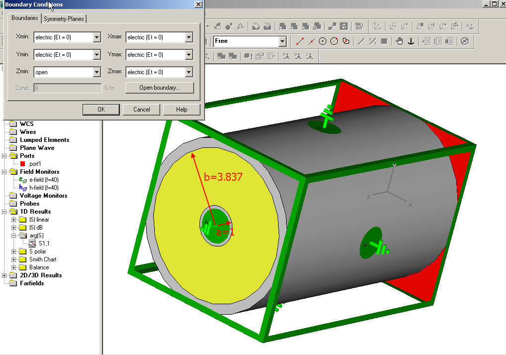
My coaxial line is a inner PEC cylinder pin with the radius of a=1mm, and an cylinder PEC shell with the inner radius b=3.83.
The material between the inner pin and out shell is vacumm.
the CST model is as follows

The calculated port line impedance is 80.694ohm, which is in accordance with the analytical result.
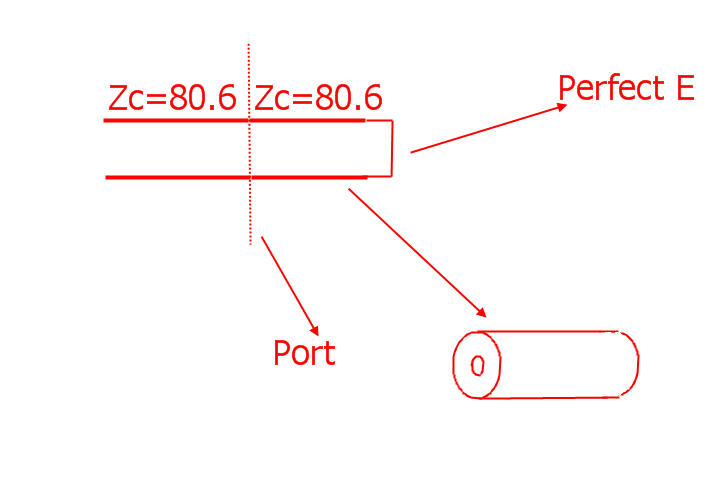
I set a port at one side of the coaxial and the other side as Perfect E boundary.
Now I assume this device model is equal to a piece of transmission line with characteristic impedance Z0=80.694, and the end load impedance is ZL=0 because of the pefect E boundary I set.
Since the port feeding transimission line is of the same line impedance with my model, then the total transmission line model I believe is as follows:
 .
.
Then I believe the S11 at the port should be equal to the reflection coeffecient
Gamma(-L)=Gamma(0)*exp(-j2kL)=-exp(-j2kL), because
Gamma(0)=(0-Zc)/(0+Zc)=-1.
This means the magnitude of the S11 should always be 1 and only the phase of the Gamma changes with the length of the transmission line. This is a very basic model of short circuited transmission line.
Then in CST I set the length of the coaxial line to be 16mm and the frequency to be 40GHz. The analytical result of the Arg(S11) should be 82.953degree, while the simulation result of Arg(S11) is 71.18degree.
I tried many value of the length of the line and the phenomenon is that when the length is small, the simulation result of the Arg(S11) is close to the analytical result,and when the length of the coaxial line is longer, the difference becomes obvious.
So my problem is whethen my equavalence of the coaxial line to the transmission line is valid. and whether the PEC boundary at one end can be equal to a short circuit load ZL=0?
Added after 1 hours 1 minutes:
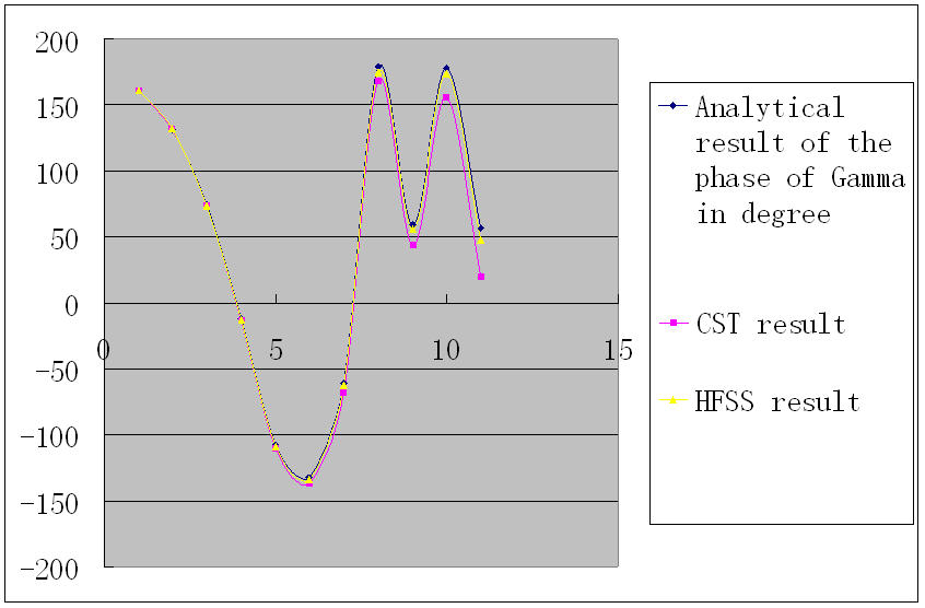
Just now I did a bunch of simulation in both CST and HFSS, and found that when the coaxial line length is becoming longer, the S11 value from CST and HFSS are becomming more and more different from the analytical result. (hope my analytical model assmuption is correct
Line Analytical
Length result CST result HFSS result
0.2mm 160.787 160.8 161
0.5mm 131.967 131.9 132
1.1mm 74.324 73.9 74.1
2mm -12.13 -13.59 -12.7
3mm -108.196 -110.4 -109
7mm -132 -137.6 -134
10mm -60.6 -68.01 -62.3
15mm 179.018 168 175
20mm 58.6912 43.96 55.7
30mm 178.037 155.9 174
50mm 56.782 19.71 47.4

and from the above figure it is also obvious that the HFSS result is more close to the analytical result than the CST result.
Hi everybody:
Just now I create a very simple coaxial line model in both CST and HFSS to study the correspondence of real waveguide to transmission line model. But the result seems confusing.
My coaxial line is a inner PEC cylinder pin with the radius of a=1mm, and an cylinder PEC shell with the inner radius b=3.83.
The material between the inner pin and out shell is vacumm.
the CST model is as follows

The calculated port line impedance is 80.694ohm, which is in accordance with the analytical result.
I set a port at one side of the coaxial and the other side as Perfect E boundary.
Now I assume this device model is equal to a piece of transmission line with characteristic impedance Z0=80.694, and the end load impedance is ZL=0 because of the pefect E boundary I set.
Since the port feeding transimission line is of the same line impedance with my model, then the total transmission line model I believe is as follows:

Then I believe the S11 at the port should be equal to the reflection coeffecient
Gamma(-L)=Gamma(0)*exp(-j2kL)=-exp(-j2kL), because
Gamma(0)=(0-Zc)/(0+Zc)=-1.
This means the magnitude of the S11 should always be 1 and only the phase of the Gamma changes with the length of the transmission line. This is a very basic model of short circuited transmission line.
Then in CST I set the length of the coaxial line to be 16mm and the frequency to be 40GHz. The analytical result of the Arg(S11) should be 82.953degree, while the simulation result of Arg(S11) is 71.18degree.
I tried many value of the length of the line and the phenomenon is that when the length is small, the simulation result of the Arg(S11) is close to the analytical result,and when the length of the coaxial line is longer, the difference becomes obvious.
So my problem is whethen my equavalence of the coaxial line to the transmission line is valid. and whether the PEC boundary at one end can be equal to a short circuit load ZL=0?
Added after 1 hours 1 minutes:
Just now I did a bunch of simulation in both CST and HFSS, and found that when the coaxial line length is becoming longer, the S11 value from CST and HFSS are becomming more and more different from the analytical result. (hope my analytical model assmuption is correct
Line Analytical
Length result CST result HFSS result
0.2mm 160.787 160.8 161
0.5mm 131.967 131.9 132
1.1mm 74.324 73.9 74.1
2mm -12.13 -13.59 -12.7
3mm -108.196 -110.4 -109
7mm -132 -137.6 -134
10mm -60.6 -68.01 -62.3
15mm 179.018 168 175
20mm 58.6912 43.96 55.7
30mm 178.037 155.9 174
50mm 56.782 19.71 47.4

and from the above figure it is also obvious that the HFSS result is more close to the analytical result than the CST result.
