Continue to Site

Welcome to EDAboard.com

Welcome to our site! EDAboard.com is an international Electronics Discussion Forum focused on EDA software, circuits, schematics, books, theory, papers, asic, pld, 8051, DSP, Network, RF, Analog Design, PCB, Service Manuals... and a whole lot more! To participate you need to register. Registration is free. Click here to register now.

How to design a low voltage current source?

Status
Not open for further replies.

walker5678

Full Member level 3
Full Member level 3
Joined
May 17, 2006
Messages
179
Helped
7
Reputation
14
Reaction score
3
Trophy points
1,298
Visit site
Activity points
2,493
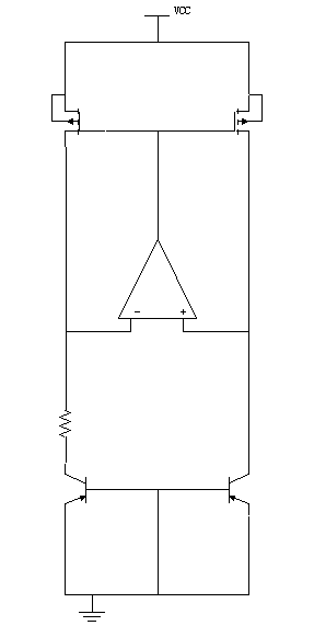
I am designing a low voltage current source, which need to work under 1.8V supply voltage, use standard 0.5um CMOS process.
Does the structure below satisfy the requirement? Can it work to generate a PTAT, and if it works, how to bias the amp ?
Appreciate your advice. Thanks.
Best regards,
17_1161594471.gif
 

Yes, the structure you show will generate a low voltage PTAT current. As for the Opamp, you can bias it from a separate const. gm core ( since it is the simplest to implement )
 

Hi elbadry
I konw that in the rail to rail input stage, there is constant gm structure, but how to use it to bias an amp? could you please describe it in more detail?

Thanks a lot.
 

fanrong said:
How about the effect of the offset of the OPAMP ?

The offset affect the current very much. If no offset,

bias current = Delta(VBE)/R = VT*ln(n)/R,

With offset,

bias current = (VT*ln(n)+VOS)/R

if choose n=8, VOS ~ +/-5mV and VT=25mV in room temp,

bias current ~ (50+/-5)mV/R, which means 10% chip-to-chip variation.
 

Status
Not open for further replies.

Part and Inventory Search

Welcome to EDABoard.com

Sponsor

Back
Top