Continue to Site

Welcome to EDAboard.com

Welcome to our site! EDAboard.com is an international Electronics Discussion Forum focused on EDA software, circuits, schematics, books, theory, papers, asic, pld, 8051, DSP, Network, RF, Analog Design, PCB, Service Manuals... and a whole lot more! To participate you need to register. Registration is free. Click here to register now.

Inductor design for SEPIC DC-DC converter

Status
Not open for further replies.

powersys

Advanced Member level 1
Joined
Nov 29, 2005
Messages
439
Helped
3
Reputation
6
Reaction score
2
Trophy points
1,298
Activity points
4,981
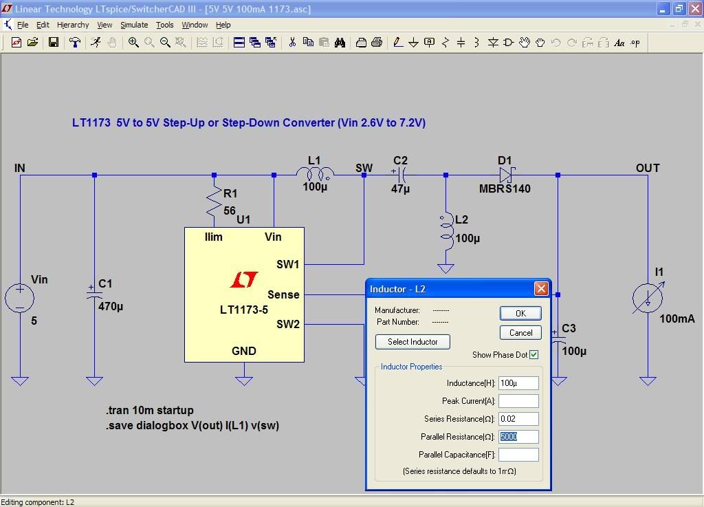
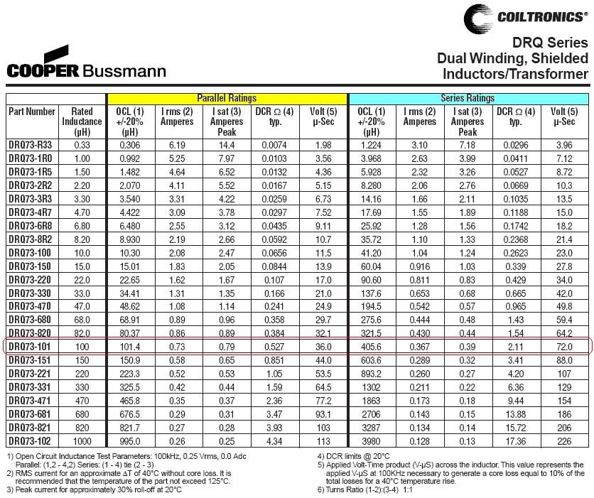
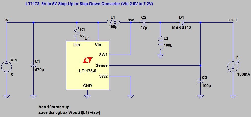
As shown in the figure below, there are two inductors, i.e. L1 and L2. Should we choose TWO individual inductors or two windings on a single core inductor for the SEPIC design?

Would someone pls advise what's the main difference (in term of performance) of two individual inductors and two windings on a single core inductor?

Is it a MUST to use two windings on a single core inductor for SEPIC design?

Thanks


LT1173SEPIC.jpg
 

The software used is SwitcherCAD III from Linear Technology. Figure A shows the default settings of L2. Pls note that the parallel resistance is 5000 Ω.

1) What do parallel resistance and series resistance mean here?
2) Do you think the parallel resistance is similar to the DCR stated in 'Parallel Ratings' column of the datasheet of DRQ series from Coiltronics as shown in Figure B?
3) If YES, why the value of this parallel resistance (i.e. 5000 Ω) is so large compared to those given in the datasheet?
4) How does the parallel resistance affect the performance of the SEPIC?


Figure A
L2Parameters.jpg
[/code]


Figure B
CoiltronicsDRQSeries.jpg
 

Status
Not open for further replies.

Part and Inventory Search

Welcome to EDABoard.com

Sponsor

Back
Top