Erchanik
Newbie level 1

HI
I am designing FB-PS ZVS step-down converter using UC3875 controller.
Actually i am beginner in field of SMPS technology but i have already created full bridge converter on base of UC3875 but without voltage feedback.
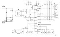
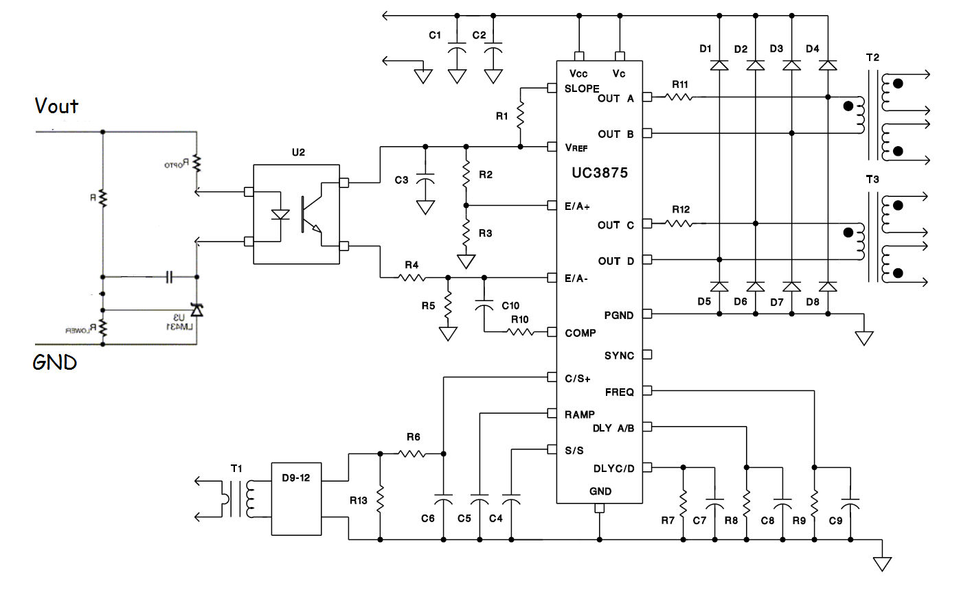
I took example from UC3875 application note, picture below
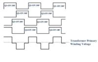
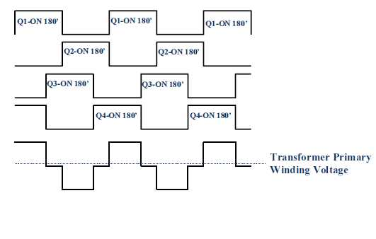
So now UC3875 just generate PWM Phase shift pulses. Diagram below is waveforms on transformer
Difference between Current mode and Voltage mode SMPS as i understand, is that you can control both current and voltage in Current mode simultaneously. (?) and in this UC3875 application example i assume is current mode
As you can see from picture Vout is connected to voltage divider and mid point connected to ADJ pin of TL431 ,than goes 4n35 optocoupler.
When output voltage rises TL431 triggers and finally on E/A- we have high voltage,
BUT!!! duty cycle DOES not decrease and respectively Vout is not stabilized!
Current coil i didn't connect yet to current sense transformer and C/S+ pin is just grounded.
As i understand from datasheet when voltage on C/S+ pin exceeds 2.5v output are just forced off and it is nothing to do with duty cycle???
Thank you!
I am designing FB-PS ZVS step-down converter using UC3875 controller.
Actually i am beginner in field of SMPS technology but i have already created full bridge converter on base of UC3875 but without voltage feedback.
I took example from UC3875 application note, picture below
So now UC3875 just generate PWM Phase shift pulses. Diagram below is waveforms on transformer
Difference between Current mode and Voltage mode SMPS as i understand, is that you can control both current and voltage in Current mode simultaneously. (?) and in this UC3875 application example i assume is current mode
As you can see from picture Vout is connected to voltage divider and mid point connected to ADJ pin of TL431 ,than goes 4n35 optocoupler.
When output voltage rises TL431 triggers and finally on E/A- we have high voltage,
BUT!!! duty cycle DOES not decrease and respectively Vout is not stabilized!
Current coil i didn't connect yet to current sense transformer and C/S+ pin is just grounded.
As i understand from datasheet when voltage on C/S+ pin exceeds 2.5v output are just forced off and it is nothing to do with duty cycle???
Thank you!
