SHADIQUE
Member level 3

- Joined
- Dec 3, 2016
- Messages
- 54
- Helped
- 3
- Reputation
- 6
- Reaction score
- 3
- Trophy points
- 8
- Location
- New Delhi
- Activity points
- 444
Hi there,
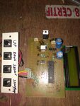
This is my real hardware circcuit shown in below

in which used component like MOC3021 (OPTOCOUPLER), BT-136(TRIAC),4 SWITCH(BUTTON),CRYSTAL 20 MHZ,PIC16F72(MICROCONTROLLER),
7805 and 16X2 LCD .
project details-
pin conncted to pic16f72 MCU as
sbit LCD_RS at RB2_bit;
sbit LCD_EN at RB3_bit;
sbit LCD_D4 at RB4_bit;
sbit LCD_D5 at RB5_bit;
sbit LCD_D6 at RB6_bit;
sbit LCD_D7 at RB7_bit;
#define buzz portc.rc3
#define up porta.ra5
#define esc porta.ra4
#define down portc.rc0
#define ent portc.rc1
#define out portc.rc7
button1(up)-increase the voltage(0 to 5v)and increase the time value.
button2(down)-decrease the voltage (5 to 0v) and decrease the time value.
button3(esc)-function select voltage or time.
button4(ent)-start/stop perform on voltafe and time for set the time or voltage
port.rc7 is connected to optocoupler.
please help me how do i do?
This is my real hardware circcuit shown in below

in which used component like MOC3021 (OPTOCOUPLER), BT-136(TRIAC),4 SWITCH(BUTTON),CRYSTAL 20 MHZ,PIC16F72(MICROCONTROLLER),
7805 and 16X2 LCD .
project details-
pin conncted to pic16f72 MCU as
sbit LCD_RS at RB2_bit;
sbit LCD_EN at RB3_bit;
sbit LCD_D4 at RB4_bit;
sbit LCD_D5 at RB5_bit;
sbit LCD_D6 at RB6_bit;
sbit LCD_D7 at RB7_bit;
#define buzz portc.rc3
#define up porta.ra5
#define esc porta.ra4
#define down portc.rc0
#define ent portc.rc1
#define out portc.rc7
button1(up)-increase the voltage(0 to 5v)and increase the time value.
button2(down)-decrease the voltage (5 to 0v) and decrease the time value.
button3(esc)-function select voltage or time.
button4(ent)-start/stop perform on voltafe and time for set the time or voltage
port.rc7 is connected to optocoupler.
please help me how do i do?


