Continue to Site

Welcome to EDAboard.com

Welcome to our site! EDAboard.com is an international Electronics Discussion Forum focused on EDA software, circuits, schematics, books, theory, papers, asic, pld, 8051, DSP, Network, RF, Analog Design, PCB, Service Manuals... and a whole lot more! To participate you need to register. Registration is free. Click here to register now.

reviewing a preamp design

Status
Not open for further replies.

Enzy

Advanced Member level 1
Joined
Mar 20, 2016
Messages
488
Helped
2
Reputation
4
Reaction score
2
Trophy points
18
Visit site
Activity points
4,607
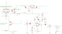
I got help from audio-guru to build this circuit in the past, I used it once but I got the circuits mixed up and had to redraw it and I built it just now but I just getting some humming out of it but I am yet to find the issue.

How does this look to you.


There may be numerous places for hum to be introduced - the first is often concerned with how/where/why the circuit is grounded and what it is connected to. It may be passing ground current between the source and the output attached devices, whatever they are? How the wiring is routed, cable shielding, proximity to AC mains and location/ orientation of the transformer (shielded or not?) all can contribute. And many other things.

I have no idea what values some of your components are, for example, the diode bridge. But, I would generally put snubber caps on each diode unless they are of the very fast switching type - otherwise you can get switching spikes introduced into the power net feeding the regulator. What is the transformer's output? The 7812 (I am assuming that is what it is) will need a few volts of "headroom" on the input side. I would also go with more than just 10uF on the output side of the regulator and be sure there was a smaller ceramic or film cap by the power pin of the TL071.. for starters.
 

I made some changes, Also I am using shielded wires. the preamp is connected to a ready made Chinese amplifier board with a 14k impedance input. I use more than once and they play really clean.

To power the preamp I am using a regular 12v iron core transformer its also used to power fans I plan to use. I am using 1amp Pn junction diodes.

my problem is that I am hearing some hums but Im not actually getting any audio output so I am assuming I did a wrong connection at some point, Where I have the stereo to monoconverter is that how I should have done it, Why I am asking is because I am wondering if the signal input will be connected to ground.


If you have a regular 12VDC power supply - use it and disconnect your transformer. diode bridge and regulator circuit and see if the hum is still present.
If it is gone, then you know the transformer, the fans, or the ground connections in your regulator circuitry are introducing the hum.
If it is gone, try reconnecting the transformer, etc but leave the fans disconnected and try that next.
Make sure you are not running this directly under a florescent tube light fixture, as that will also induce hum in any wires nearby.
Is this hum produced with anything connected to the input, or with the circuit simply sitting there with input floating? What if you ground the input to the circuit ground with a 1K resistor? What are you using to "hear" the hum from the other side? Have you tried to disconnect the shield connection from either the input or the output cable? Do you have an oscilloscope that you could use to measure the output voltage and post a picture?

Of course the diodes are PN junction diodes, but what specifically are the part numbers? The part numbers will tell us whether they are ultrafast switching, etc.
if they are standard 1N00_ diodes, they have significant capacitance and can make transient pulses as they switch on and off during AC rectification, and could benefit from 100nF capacitor (film) snubbers in parallel with each one of voltage rating at least 25V or better 50V. But, it is probably not very likely what you are hearing is coming from that particular kind of transient.

Divide and conquer!
 

I actually dont have any 12v dc power supply but I dont beleive the power supply is the issue as I am not getting any audio from the input at all its just humming, normally if there is humming in the input I would get some form of audio also (based on my experience)

I tried connecting up without input wire and hums just the same. I have a pocket scope I tested the signal input from my phone and at max i getting like about 260mv and the signal looks good (sinewave).

the output isnt correct though as its too low, at max Im getting 70mv but the signal isnt noisy either, its a clean enough sinewave.

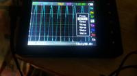
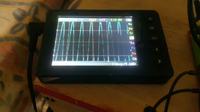
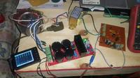
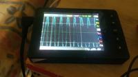
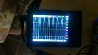
I have some images when I connected up to the amplifier board.


- - - Updated - - -

sorry about the poor quality

- - - Updated - - -

also Im using regular 1n4007....

- - - Updated - - -

i got it working just now, I was still figuring something is wrong with the stereo to mono converter circuit so I took one leg off and connected it to GND and it worked with no hum and audio came out. So the only problem with that is that I wouldnt be utilizing the full stereo signal
 

If I understand what you did, that is because the left and right inputs you have are providing a low frequency/DC path to each other on your input device outputs, and they are not in perfect balance, and the 20Kohm DC connection is not sufficient isolation and a loop is created where you do not want one to be. So, something must be made to isolate them from feeding into each other. One way you might do this is to insert voltage follower configured op amps (you can try basically inserting them between your 10K resistors and the junction you've made between them to feed into the potentiometer). So, each (left, right) input channel goes through 10K ohm into voltage follower op amp (you can put a 1K resistor on output of each voltage follower for testing purposes and to avoid problems from cascading), and then tie the output ends of the 1K resistors into the potentiometer connection. You can add some small local capacitors to the power connections on the voltage follower op amps. You might have to tweak resistor values and/or add some filtering caps, but this will provide greater isolation between the outputs of your source device/inputs to your converter.
HOWEVER, to do this as I have described above, will require you to have bipolar power supply rails on your board, as this is before your input DC blocking cap!

Another thing you might try, but it may not work so well, is to add ~10uF caps in series with each one of your 10K input resistors - this would at least block DC imbalances from the outputs feeding into your circuit inputs, but still allow audio frequency signals to pass. But, the hum may still be coming in that frequency range.

The proximity of those unshielded transformers and their wiring to the AC mains is truly frightening in appearance.

Good luck!
 
Last edited:

You say yo disconnected one channel at the input and the Hum dissipated ?
This means you have a bad channel with a hum or a very poor quality audio source that is incapable of supplying some 500ish micro-amps. try inserting a capacitor at each separate input, like a 10uF each. This will prevent any DC current between each output. It may remove the stress on your output source and eliminate the Hum.
 

The TL071 and many other opamps oscillate at a high frequency when they are driving the capacitance of a shielded output cable. Add a 100 ohm resistor from the output of the opamp to its output coupling capacitor C1 to fix it.
Capacitors C1, c2 and C5 do not show their polarity on your schematic so they might be backwards.

- - - Updated - - -

What are the input signals to this preamp coming from? I hope they are not the bridged outputs of the Chinese power amp that are not grounded. Each speaker wire from a bridged amplifier has high current signals and they have a DC voltage that is bad for your volume control.

Your wiring photo has nothing labelled. Input, output, AC or DC power wires.
Your 'scope has the signal so high that it is above and below the screen. What is the input to the scope??
 

The output of the chinese amplifier goes to the speakers. currently for testing... the input to the preamp is coming from either a phone or a laptop.

in the images sent the scope's input was coming from the output of the chinese amplifier.


- - - Updated - - -

ok I have the scope connected up now the output of the chinese amp with no input signal connected to the preamp also I did the same test without preamp connected, results w ere thew same am getting 480mv RMS, 1.36V peak to peak, Average voltage is 60 to 160mv.

now testing the preamp itself I applied a 1khz test tone from my phone I am getting 20% dut cycl, 2.56V RMS, AVG volt is 0V, Peak to Peak V is 7.4V.

input from my phone to preamp is 240mv RMS, Peak to Peak is 480mv

- - - Updated - - -

The Image is from the preamp at 1khz 2.56V
 

Attachments

  • IMG_001.BMP
    38 KB · Views: 109

The sinewave shown on your scope has digital steps because it or the amplifier (or both) are Cheap.
EDIT: From the preamp? But it is analog, not digital so the steps are from your 'scope.
 

Attachments

  • digital steps.png
    digital steps.png
    47.6 KB · Views: 121

no doubt the amp is cheap, the scope is a little pocket scope I made that known also, So in other words what are saying besides they are cheap?

Also its a class D amp the scope can be adjusted for the wave to look smooth also. It would be much aprreciated also If I could get aid to build a proper amplifier, something with a good power rating, the one I am using now is 700W @4 ohm.
 

what are saying besides they are cheap?
They have very poor quality.

the scope can be adjusted for the wave to look smooth
A simple lowpass filter smooths a waveform by cutting its important high frequencies that you do not want to do with a 'scope. You want the 'scope to show you any high frequency oscillation or clipping of a waveform.
 

I'm kinda lost, Im seeing a sinewave with the scope, which looks OK, if it's clipping it square if it's not clipping then it's a sinewave.
So I guess that's concluded.... Not sure if that's what your trying to say.


The amplifier is cheap so I would assume that's why I am getting 480mv when no audio is playing.

The preamp is clean when using the scope to test it when there is no signal at the input then there is no voltage at the output.

Also I was asking if I can get help making a class D amplifier is that a possibility?
 

I'm kinda lost, Im seeing a sinewave with the scope, which looks OK
The preamp is clean when using the scope to test it when there is no signal at the input then there is no voltage at the output.
The waveform you showed at the output of the preamp is not a sinewave, instead it is digital steps. You cannot see if the sinewave is clipping and you cannot see high frequency oscillation.
My 'scope is analog, not digital and it shows a sinewave, clipping or oscillation very clearly.

I was asking if I can get help making a class D amplifier is that a possibility?
Why do you want class-D? Most amplifiers and all my amplifiers are class-AB and do not produce an output when there is no input.
 

Those images were when I was having problems with the preamp no grounding connections were made for the input signal so I was just getting humming from the output, I stated after after I found the issue that the preamp is now clean if no input then there is no output 0V, said it more than once so thats what kep confusing me that you keep mentioning the wave form, not to say the wave is perfectly sine but this preamp was developed with your help in the past I guess I could work on something better but thats why I normally ask for help here.

I use cladd D because of the effeciency I have a class AB amp that I use already but normally for class D I have to buy a chinese amp and it would be good if I could build a CLass D amp, building a class AB amp If I need say 1000w the circuit tends to be very big and require veryy big heat sinks but with the class D since its more efficient I tend to use smaller heatsinks and smaller circuit based on what I have seen, but I would take the help to build anyone of the designs that Ill get help for.

- - - Updated - - -

The chinese amp is cheap yes so I guess its producing signal when there is no input that cant be helped but I would love to make one for myself.
 

Last year you talked about using a 1000W amplifier in a car. But if the Watts are real then that is crazy, it will break all the windows and destroy your hearing.
Maybe you are talking about 1000 Whats that are not real Watts.

I bought a Name Brand (Sylvania) 2.1 audio system (2 satellite speakers and one subwoofer speaker) that was on sale for $19.99US. It was advertised as producing a total output of 150 Watts and 75W RMS. It sounds good but no way it produces that much power. Inside is a little power transformer marked 9VAC/1.1A (9.9W) but the amplifiers are class-AB and get hot so there is about 4W of heating then the amplifiers produce a total output of only 9.9W - 4W= 5.9W, not 150W.

150/5.9= 25.4 times so maybe your 1000 Whats car amplifier produces only 1000/25.4= 39.4 Watts.
 

I'm in no way speaking about a car amplifier, I made a post last year asking about a car amplifier and this is a different post.... This is to be used outdoors on mains 110v power.

You made a statement like that once before also and even though I understand what your saying but I find it hard to beleive that the bug manufacturers put such way off specs on their products, I know they are what they say it is but it can't be way off

- - - Updated - - -

for example I have listened amplifiers like this with very high wattage because in my country we have alot of sound systems and the big established sounds use very power amplifiers.

https://www.powersoft-audio.com/en/touring/k-series#K20

check this amp

- - - Updated - - -

we play crazy music out here in large set ups, the music boxes are set up in coloums and our standard setup is 4 colums where we use 32 bass speakers,

imagine trying to blast 32 of these
https://www.usspeaker.com/eighteensound-18NLW9600-1.htm

I would need crazy power, now I see setups just like this with 32 18" 3000w bass speakers and 10,000w amplifiers playing bass at times even two 10,000w amplifiers are used
 

Could you explain what you think about the amplifier I showed you and similar and also the speaker and others similar.
 

The Powersoft amplifiers use fake EIAJ testing which has only short duration bursts of output, not continuous output that is used in most good amplifiers. Also it is at only 1kHz, not over the entire hearing range of frequencies. Also it is with a saturated squarewave signal. Most or all people can hear the 1% of clipping distortion their tests use but a saturated squarewave has 50% distortion.

The woofer speakers are lightweight which is not good for a high power speaker.

I have never been interested by a deafening rock concert.

Here is an amplifier that has a few power ratings and a description of the EIAJ rating:

- - - Updated - - -

Here is another description of EIAJ power (the J is Japanese):
 

Attachments

  • EIAJ amplifier power.png
    EIAJ amplifier power.png
    39.7 KB · Views: 117
  • EIAJ.png
    EIAJ.png
    9.4 KB · Views: 122

Status
Not open for further replies.

Similar threads

Part and Inventory Search

Welcome to EDABoard.com

Sponsor

Back
Top