Continue to Site

Welcome to EDAboard.com

Welcome to our site! EDAboard.com is an international Electronics Discussion Forum focused on EDA software, circuits, schematics, books, theory, papers, asic, pld, 8051, DSP, Network, RF, Analog Design, PCB, Service Manuals... and a whole lot more! To participate you need to register. Registration is free. Click here to register now.

[moved] Arduino / LCD / '595 cascade

Status
Not open for further replies.

Adri67

Junior Member level 2
Joined
Aug 11, 2014
Messages
24
Helped
0
Reputation
0
Reaction score
0
Trophy points
1
Visit site
Activity points
267
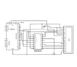
I am using the standard Arduino Liquidcrystal595.h with 3-wire connect successfully.
My only problem is to extend this to use 5 additional outputs from a 2nd '595.
How to modify the circuit while still using the existing LCD (HB44870) but adding the 2nd '595 to make use of additional outputs?
And then how to modify the sketch?
 

This part is working successfully.
LCD595.jpg

#include <LiquidCrystal595.h> // the library
LiquidCrystal595 lcd(7,8,9); // datapin, latchpin, clockpin

void setup() {
lcd.begin(16,2); // LCD 1602

lcd.clear();
lcd.setCursor(0,0);
lcd.print("LCD 3-wire");
lcd.setCursor(0,1);
lcd.print("communicator");
}

void loop() {
// not used.

Example of what I'm looking at**broken link removed**.
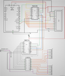
But instead the 1st '595 must run the LCD as per above and the 2nd '595 outputs switched on command from Arduino.
 

Attachments

  • cascade595a.jpg
    cascade595a.jpg
    50.5 KB · Views: 251

I'm not sure what you mean, but if you want two LCDs...

Code:
#include <LiquidCrystal595.h> // the library
LiquidCrystal595 lcd1(7,8,9); // datapin, latchpin, clockpin

LiquidCrystal595 lcd2(4,5,6); // datapin, latchpin, clockpin

void setup() {
lcd1.begin(16,2); // LCD 1602
lcd2.begin(16,2); // LCD 1602

lcd1.clear();
lcd2.clear();
lcd1.setCursor(0,0);
lcd2.setCursor(0,0);
lcd1.print("LCD 3-wire");
lcd2.print("Second LCD");
lcd1.setCursor(0,1);
lcd2.setCursor(0,1);
lcd1.print("communicator");
lcd2.print("is here");
}
you can change 4,5,6 pins to other suitable...
 

hi Alloy,
Not really but you have given me another useful clue...!
My system is split into 2 parts :
(a) control unit, with Arduino, input, output, etc, and
(b) display unit with LCD, 2 buttons, piezo beeper and 6 LEDs.
The 2 parts are interconnected by one 8-core cable, so I'm severely limited.
I.e. +5V, GND, 2 buttons, 3 for '595, only 1 remaining wire.
By cascading 2 x '595 I don't need extra wires for my 6 LEDs and piezo.

I now have this test rig working.

// for 2 x 74HC595 ... (20160924)

int SER_Pin = 8; // 14 / 595
int RCLK_Pin = 9; // 12 / 595
int SRCLK_Pin = 10; //11 / 595

boolean reg [16];

void setup() {

pinMode (SER_Pin, OUTPUT);
pinMode (RCLK_Pin, OUTPUT);
pinMode (SRCLK_Pin, OUTPUT);

//reset all register pins
clearReg ();
writeReg ();
}

void clearReg () {
for(int i = 15; i >= 0; i--) {
reg = LOW;
}
}

void writeReg () {

digitalWrite (RCLK_Pin, LOW);

for (int i = 15; i >= 0; i--) {
digitalWrite (SRCLK_Pin, LOW);

int val = reg ;

digitalWrite (SER_Pin, val);
digitalWrite (SRCLK_Pin, HIGH);

}
digitalWrite (RCLK_Pin, HIGH);

}

void K(int index, int value) {
reg [index] = value;
}

void loop() {

K (0, 0);
K (1, 1);
K (2, 0);
K (3, 0);
K (4, 0);
K (5, 0);
K (6, 0);
K (7, 1);
K (8, 0);
K (9, 0);
K (10, 0);
K (11, 0);
K (12, 1);
K (13, 0);
K (14, 0);
K (15, 1);

writeReg();
}

so I imagine K0 ...K7 for LCD (I'll call it '595a) and K8+ for LEDs & piezo (on '595b).

Looking at Liquidcrystal595.cpp ....
Code:
/* -----------------------------------------------------------------------------------
 * Adaption of the LiquidCrystal library shipped with Arduino 22
 * for use with 74HC595 shift register adapter board found on:
 * http://www.stephenhobley.com
 
 * Code adaption by Steve Hobley - February 2011

 /*---Shift Register 74HC595---
 * [SR Pin 14 (DS)]    to Arduino pin - Yellow wire [datapin]
 * [SR Pin 12 (ST_CP)] to Arduino pin - Green wire  [latchpin]
 * [SR Pin 11 (SH_CP)] to Arduino pin - White wire  [clockpin]
 * Black wire to Ground
 * Red wire to +5v

 -----Shift Reg to LCD--------
 * SR Pin 15  - ENABLE              10000000
 * SR Pin 1   - D4                        00000010 
 * SR Pin 2   - D5			   00000100
 * SR Pin 3   - D6			   00001000
 * SR Pin 4   - D7			  00010000
 * SR Pin 5   - MOSFET / LED1 00100000
 * SR Pin 6   - LED 2                  01000000
 * SR Pin 7   - RS                       00000001
 *
 * -----------------------------------------------------------------------------------
 */
// 595 mappings - LED1 is also the backlight controller
#define ENABLE_PIN  B00000001
#define RS_PIN		B10000000
#define LED1_PIN    B00100000
#define LED2_PIN    B01000000
#define DATABITS	B00011110

#define PIN_D4		B00000010
#define PIN_D5		B00000100
#define PIN_D6		B00001000
#define PIN_D7		B00010000

#include "LiquidCrystal595.h"

#include <stdio.h>
#include <string.h>
#include <inttypes.h>
#include "WProgram.h"

// When the display powers up, it is configured as follows:
//
// 1. Display clear
// 2. Function set: 
//    DL = 1; 8-bit interface data 
//    N = 0; 1-line display 
//    F = 0; 5x8 dot character font 
// 3. Display on/off control: 
//    D = 0; Display off 
//    C = 0; Cursor off 
//    B = 0; Blinking off 
// 4. Entry mode set: 
//    I/D = 1; Increment by 1 
//    S = 0; No shift 
//
// Note, however, that resetting the Arduino doesn't reset the LCD, so we
// can't assume that its in that state when a sketch starts (and the
// LiquidCrystal constructor is called).

LiquidCrystal595::LiquidCrystal595(uint8_t datapin, uint8_t latchpin, uint8_t clockpin)
{
  init(datapin, latchpin, clockpin);
}

// Performs the shift, MSB first 
void LiquidCrystal595::shift595()
{
    digitalWrite(_latchpin, LOW);
    shiftOut(_datapin, _clockpin, MSBFIRST, _register);  
    digitalWrite(_latchpin, HIGH);
}

void LiquidCrystal595::init(uint8_t datapin, uint8_t latchpin, uint8_t clockpin)
{
  _datapin  = datapin;
  _latchpin = latchpin;
  _clockpin = clockpin;

   pinMode(_datapin, OUTPUT);
   pinMode(_latchpin, OUTPUT);
   pinMode(_clockpin, OUTPUT);
   
   _displayfunction = LCD_4BITMODE | LCD_1LINE | LCD_5x8DOTS;
  
  begin(16, 1);  
}

void LiquidCrystal595::begin(uint8_t cols, uint8_t lines, uint8_t dotsize) 
{
  
  if (lines > 1) 
  {
    _displayfunction |= LCD_2LINE;
  }
  _numlines = lines;
  _currline = 0;

  // for some 1 line displays you can select a 10 pixel high font
  if ((dotsize != 0) && (lines == 1)) {
    _displayfunction |= LCD_5x10DOTS;
  }

  // SEE PAGE 45/46 FOR INITIALIZATION SPECIFICATION!
  // according to datasheet, we need at least 40ms after power rises above 2.7V
  // before sending commands. Arduino can turn on way befer 4.5V so we'll wait 50
  delayMicroseconds(50000); 
  // Now we pull both RS and R/W low to begin commands
  
  setRSPin(LOW);
  setEPin(LOW);
  shift595();
  
  //digitalWrite(_rs_pin, LOW);
  //digitalWrite(_enable_pin, LOW);
  
  //if (_rw_pin != 255) { 
  //  digitalWrite(_rw_pin, LOW);
  //}
  
  //put the LCD into 4 bit or 8 bit mode
  if (! (_displayfunction & LCD_8BITMODE)) 
  {
    // this is according to the hitachi HD44780 datasheet
    // figure 24, pg 46

    // we start in 8bit mode, try to set 4 bit mode
    write4bits(0x03);
    delayMicroseconds(4500); // wait min 4.1ms

    // second try
    write4bits(0x03);
    delayMicroseconds(4500); // wait min 4.1ms
    
    // third go!
    write4bits(0x03); 
    delayMicroseconds(150);

    // finally, set to 4-bit interface
    write4bits(0x02); 
  } else {
    // this is according to the hitachi HD44780 datasheet
    // page 45 figure 23

    // Send function set command sequence
    command(LCD_FUNCTIONSET | _displayfunction);
    delayMicroseconds(4500);  // wait more than 4.1ms

    // second try
    command(LCD_FUNCTIONSET | _displayfunction);
    delayMicroseconds(150);

    // third go
    command(LCD_FUNCTIONSET | _displayfunction);
  }

  // finally, set # lines, font size, etc.
  command(LCD_FUNCTIONSET | _displayfunction);  

  // turn the display on with no cursor or blinking default
  _displaycontrol = LCD_DISPLAYON | LCD_CURSOROFF | LCD_BLINKOFF;  
  display();

  // clear it off
  clear();

  // Initialize to default text direction (for romance languages)
  _displaymode = LCD_ENTRYLEFT | LCD_ENTRYSHIFTDECREMENT;
  // set the entry mode
  command(LCD_ENTRYMODESET | _displaymode);

}

/********** high level commands, for the user! */
void LiquidCrystal595::clear()
{
  command(LCD_CLEARDISPLAY);  // clear display, set cursor position to zero
  delayMicroseconds(2000);  // this command takes a long time!
}

void LiquidCrystal595::home()
{
  command(LCD_RETURNHOME);  // set cursor position to zero
  delayMicroseconds(2000);  // this command takes a long time!
}

void LiquidCrystal595::setCursor(uint8_t col, uint8_t row)
{
  int row_offsets[] = { 0x00, 0x40, 0x14, 0x54 };
  if ( row > _numlines ) {
    row = _numlines-1;    // we count rows starting w/0
  }
  
  command(LCD_SETDDRAMADDR | (col + row_offsets[row]));
}

// Turn the display on/off (quickly)
void LiquidCrystal595::noDisplay() {
  _displaycontrol &= ~LCD_DISPLAYON;
  command(LCD_DISPLAYCONTROL | _displaycontrol);
}
void LiquidCrystal595::display() {
  _displaycontrol |= LCD_DISPLAYON;
  command(LCD_DISPLAYCONTROL | _displaycontrol);
}

// Turns the underline cursor on/off
void LiquidCrystal595::noCursor() {
  _displaycontrol &= ~LCD_CURSORON;
  command(LCD_DISPLAYCONTROL | _displaycontrol);
}
void LiquidCrystal595::cursor() {
  _displaycontrol |= LCD_CURSORON;
  command(LCD_DISPLAYCONTROL | _displaycontrol);
}

// Turn on and off the blinking cursor
void LiquidCrystal595::noBlink() {
  _displaycontrol &= ~LCD_BLINKON;
  command(LCD_DISPLAYCONTROL | _displaycontrol);
}
void LiquidCrystal595::blink() {
  _displaycontrol |= LCD_BLINKON;
  command(LCD_DISPLAYCONTROL | _displaycontrol);
}

// These commands scroll the display without changing the RAM
void LiquidCrystal595::scrollDisplayLeft(void) {
  command(LCD_CURSORSHIFT | LCD_DISPLAYMOVE | LCD_MOVELEFT);
}
void LiquidCrystal595::scrollDisplayRight(void) {
  command(LCD_CURSORSHIFT | LCD_DISPLAYMOVE | LCD_MOVERIGHT);
}

// This is for text that flows Left to Right
void LiquidCrystal595::leftToRight(void) {
  _displaymode |= LCD_ENTRYLEFT;
  command(LCD_ENTRYMODESET | _displaymode);
}

// This is for text that flows Right to Left
void LiquidCrystal595::rightToLeft(void) {
  _displaymode &= ~LCD_ENTRYLEFT;
  command(LCD_ENTRYMODESET | _displaymode);
}

// This will 'right justify' text from the cursor
void LiquidCrystal595::autoscroll(void) {
  _displaymode |= LCD_ENTRYSHIFTINCREMENT;
  command(LCD_ENTRYMODESET | _displaymode);
}

// This will 'left justify' text from the cursor
void LiquidCrystal595::noAutoscroll(void) {
  _displaymode &= ~LCD_ENTRYSHIFTINCREMENT;
  command(LCD_ENTRYMODESET | _displaymode);
}

// Allows us to fill the first 8 CGRAM locations
// with custom characters
void LiquidCrystal595::createChar(uint8_t location, uint8_t charmap[]) {
  location &= 0x7; // we only have 8 locations 0-7
  command(LCD_SETCGRAMADDR | (location << 3));
  for (int i=0; i<8; i++) {
    write(charmap[i]);
  }
}

/*********** mid level commands, for sending data/cmds */

inline void LiquidCrystal595::command(uint8_t value) {
  send(value, LOW);
}

inline void LiquidCrystal595::write(uint8_t value) {
  send(value, HIGH);
}

/************ low level data pushing commands **********/

// write either command or data, with automatic 4/8-bit selection
void LiquidCrystal595::send(uint8_t value, uint8_t mode) 
{
  setRSPin(mode);
  shift595();
  
  //digitalWrite(_rs_pin, mode);

  // if there is a RW pin indicated, set it low to Write
  //if (_rw_pin != 255) { 
  //  digitalWrite(_rw_pin, LOW);
  //}
  
  if (_displayfunction & LCD_8BITMODE) 
  {
    write8bits(value); 
  } 
  else 
  {
    write4bits(value>>4);
    write4bits(value);
  }
}

void LiquidCrystal595::pulseEnable(void) 
{
   // LOW / HIGH / LOW of ENABLE_PIN
  setEPin(LOW);   // LOW
  shift595();
  
  delayMicroseconds(1);
  setEPin(HIGH);    // HIGH
  shift595();
  
  delayMicroseconds(1); // enable pulse must be >450ns
  
  setEPin(LOW);   // LOW
  shift595();
  delayMicroseconds(100);  // commands need > 37us to settle
}

void LiquidCrystal595::write4bits(uint8_t value) 
{
  int val_nibble= value & 0x0F;  //clean the value.  (unnecessary)
	
  setD4Pin(val_nibble & 01);
  val_nibble >>= 1;
  setD5Pin(val_nibble & 01);
  val_nibble >>= 1;
  setD6Pin(val_nibble & 01);
  val_nibble >>= 1;
  setD7Pin(val_nibble & 01);
  
  pulseEnable();
}

void LiquidCrystal595::write8bits(uint8_t value) 
{
  return;
  // Should not be used
}

// Accessor functions --------------------------------------------------------
void LiquidCrystal595::setLED1Pin(uint8_t pinValue)
{
	if (pinValue == HIGH)
	{
		_register |= LED1_PIN;    // HIGH
	}
	else
	{
		_register &= ~LED1_PIN;   // LOW
	}
}

void LiquidCrystal595::setLED2Pin(uint8_t pinValue)
{
	if (pinValue == HIGH)
	{
		_register |= LED2_PIN;    // HIGH
	}
	else
	{
		_register &= ~LED2_PIN;   // LOW
	}
}

void LiquidCrystal595::setEPin(uint8_t pinValue)
{
	if (pinValue == HIGH)
	{
		_register |= ENABLE_PIN;    // HIGH
	}
	else
	{
		_register &= ~ENABLE_PIN;   // LOW
	}
}

void LiquidCrystal595::setD4Pin(uint8_t pinValue)
{
	if (pinValue == HIGH)
	{
		_register |= PIN_D4;    // HIGH
	}
	else
	{
		_register &= ~PIN_D4;   // LOW
	}
}

void LiquidCrystal595::setD5Pin(uint8_t pinValue)
{
	if (pinValue == HIGH)
	{
		_register |= PIN_D5;    // HIGH
	}
	else
	{
		_register &= ~PIN_D5;   // LOW
	}
}
void LiquidCrystal595::setD6Pin(uint8_t pinValue)
{
	if (pinValue == HIGH)
	{
		_register |= PIN_D6;    // HIGH
	}
	else
	{
		_register &= ~PIN_D6;   // LOW
	}
}
void LiquidCrystal595::setD7Pin(uint8_t pinValue)
{
	if (pinValue == HIGH)
	{
		_register |= PIN_D7;    // HIGH
	}
	else
	{
		_register &= ~PIN_D7;   // LOW
	}
}

void LiquidCrystal595::setRSPin(uint8_t pinValue)
{
	if (pinValue == HIGH)
	{
		_register |= RS_PIN;    // HIGH
	}
	else
	{
		_register &= ~RS_PIN;   // LOW
	}
}
If I'm on the right track I imagine that connecting K0 ... K7 should happen here somewhere ...
Code:
// 595 mappings - LED1 is also the backlight controller
#define ENABLE_PIN     B00000001
#define RS_PIN		B10000000
#define LED1_PIN          B00100000
#define LED2_PIN          B01000000
#define DATABITS   	B00011110

#define PIN_D4		B00000010
#define PIN_D5		B00000100
#define PIN_D6		B00001000
#define PIN_D7		B00010000
but how to do that beats me for now.
Also, should one interfere/muddle with the Liquidcrystal595 library? (perhaps rename a "new" library? Or can this be done in the normal code leaving that library intact, and if so, how?
(Of course I could have saved 2 outputs using the setLEDxPin on '595a, but what the heck...?)

Thanks and very good wishes.
 

Hi,

I hope I understand right:
* two 595 connected in series:
* MOSI --> 595A_SER (LCD)
* 595A_QH´--> 595B_SER
* (optionlal: 595B_QH´--> MISO)
* all other control lines in parallel to both 595

Software:
* activate chipselect
* write 8 bits for 595B
* write 8 bits for 595A
* deactivete chipselect

Klaus
 

Not quite. I want to use one '595 for the LCD (which I call '595a) and 2nd ('595b) for additional LED indicators.
I have a test rig working :
Code:
// for 2 x 74HC595   (20160924)

int SER_Pin = 8;   // 14 / 595
int RCLK_Pin = 9;  // 12 / 595
int SRCLK_Pin = 10; //11 / 595

boolean reg [16];

void setup()  {
  
  pinMode (SER_Pin, OUTPUT);
  pinMode (RCLK_Pin, OUTPUT);
  pinMode (SRCLK_Pin, OUTPUT);

  //reset all register pins
  clearReg ();
  writeReg ();
}               


void clearReg () {
  for(int i = 15; i >=  0; i--) {
    reg [i] = LOW;
  }
} 

void writeReg ()  {

  digitalWrite (RCLK_Pin, LOW);

  for (int i = 15; i >=  0; i--)  {
    digitalWrite (SRCLK_Pin, LOW);

    int val = reg [i];

    digitalWrite (SER_Pin, val);
    digitalWrite (SRCLK_Pin, HIGH);
  }
  digitalWrite (RCLK_Pin, HIGH);
}

void K(int index, int value)  {
  reg [index] = value;
}

void loop(){

  K (0, 0);
  K (1, 1);
  K (2, 0);
  K (3, 0);
  K (4, 0);
  K (5, 0);
  K (6, 0);
  K (7, 1);
  K (8, 0);
  K (9, 0);
  K (10, 0);
  K (11, 0);
  K (12, 1);
  K (13, 0);
  K (14, 0);
  K (15, 1);

  writeReg();  
}

... and then looking at Liquidcrystal595.cpp ...

Code:
/* -----------------------------------------------------------------------------------
 * Adaption of the LiquidCrystal library shipped with Arduino 22
 * for use with 74HC595 shift register adapter board found on:
 * http://www.stephenhobley.com
 
 * Code adaption by Steve Hobley - February 2011

 /*---Shift Register 74HC595---
 * [SR Pin 14 (DS)]    to Arduino pin - Yellow wire [datapin]
 * [SR Pin 12 (ST_CP)] to Arduino pin - Green wire  [latchpin]
 * [SR Pin 11 (SH_CP)] to Arduino pin - White wire  [clockpin]
 * Black wire to Ground
 * Red wire to +5v

 -----Shift Reg to LCD--------
 * SR Pin 15  - ENABLE        10000000
 * SR Pin 1   - D4            00000010 
 * SR Pin 2   - D5			  00000100
 * SR Pin 3   - D6			  00001000
 * SR Pin 4   - D7			  00010000
 * SR Pin 5   - MOSFET / LED1 00100000
 * SR Pin 6   - LED 2         01000000
 * SR Pin 7   - RS            00000001
 *
 * -----------------------------------------------------------------------------------
 */
// 595 mappings - LED1 is also the backlight controller
#define ENABLE_PIN  B00000001
#define RS_PIN		B10000000
#define LED1_PIN         B00100000
#define LED2_PIN         B01000000
#define DATABITS         B00011110

#define PIN_D4		B00000010
#define PIN_D5		B00000100
#define PIN_D6		B00001000
#define PIN_D7    		B00010000

#include "LiquidCrystal595.h"

#include <stdio.h>
#include <string.h>
#include <inttypes.h>
#include "WProgram.h"

// When the display powers up, it is configured as follows:
//
// 1. Display clear
// 2. Function set: 
//    DL = 1; 8-bit interface data 
//    N = 0; 1-line display 
//    F = 0; 5x8 dot character font 
// 3. Display on/off control: 
//    D = 0; Display off 
//    C = 0; Cursor off 
//    B = 0; Blinking off 
// 4. Entry mode set: 
//    I/D = 1; Increment by 1 
//    S = 0; No shift 
//
// Note, however, that resetting the Arduino doesn't reset the LCD, so we
// can't assume that its in that state when a sketch starts (and the
// LiquidCrystal constructor is called).

LiquidCrystal595::LiquidCrystal595(uint8_t datapin, uint8_t latchpin, uint8_t clockpin)
{
  init(datapin, latchpin, clockpin);
}

// Performs the shift, MSB first 
void LiquidCrystal595::shift595()
{
    digitalWrite(_latchpin, LOW);
    shiftOut(_datapin, _clockpin, MSBFIRST, _register);  
    digitalWrite(_latchpin, HIGH);
}

void LiquidCrystal595::init(uint8_t datapin, uint8_t latchpin, uint8_t clockpin)
{
  _datapin  = datapin;
  _latchpin = latchpin;
  _clockpin = clockpin;

   pinMode(_datapin, OUTPUT);
   pinMode(_latchpin, OUTPUT);
   pinMode(_clockpin, OUTPUT);
   
   _displayfunction = LCD_4BITMODE | LCD_1LINE | LCD_5x8DOTS;
  
  begin(16, 1);  
}

void LiquidCrystal595::begin(uint8_t cols, uint8_t lines, uint8_t dotsize) 
{
  
  if (lines > 1) 
  {
    _displayfunction |= LCD_2LINE;
  }
  _numlines = lines;
  _currline = 0;

  // for some 1 line displays you can select a 10 pixel high font
  if ((dotsize != 0) && (lines == 1)) {
    _displayfunction |= LCD_5x10DOTS;
  }

  // SEE PAGE 45/46 FOR INITIALIZATION SPECIFICATION!
  // according to datasheet, we need at least 40ms after power rises above 2.7V
  // before sending commands. Arduino can turn on way befer 4.5V so we'll wait 50
  delayMicroseconds(50000); 
  // Now we pull both RS and R/W low to begin commands
  
  setRSPin(LOW);
  setEPin(LOW);
  shift595();
  
  //digitalWrite(_rs_pin, LOW);
  //digitalWrite(_enable_pin, LOW);
  
  //if (_rw_pin != 255) { 
  //  digitalWrite(_rw_pin, LOW);
  //}
  
  //put the LCD into 4 bit or 8 bit mode
  if (! (_displayfunction & LCD_8BITMODE)) 
  {
    // this is according to the hitachi HD44780 datasheet
    // figure 24, pg 46

    // we start in 8bit mode, try to set 4 bit mode
    write4bits(0x03);
    delayMicroseconds(4500); // wait min 4.1ms

    // second try
    write4bits(0x03);
    delayMicroseconds(4500); // wait min 4.1ms
    
    // third go!
    write4bits(0x03); 
    delayMicroseconds(150);

    // finally, set to 4-bit interface
    write4bits(0x02); 
  } else {
    // this is according to the hitachi HD44780 datasheet
    // page 45 figure 23

    // Send function set command sequence
    command(LCD_FUNCTIONSET | _displayfunction);
    delayMicroseconds(4500);  // wait more than 4.1ms

    // second try
    command(LCD_FUNCTIONSET | _displayfunction);
    delayMicroseconds(150);

    // third go
    command(LCD_FUNCTIONSET | _displayfunction);
  }

  // finally, set # lines, font size, etc.
  command(LCD_FUNCTIONSET | _displayfunction);  

  // turn the display on with no cursor or blinking default
  _displaycontrol = LCD_DISPLAYON | LCD_CURSOROFF | LCD_BLINKOFF;  
  display();

  // clear it off
  clear();

  // Initialize to default text direction (for romance languages)
  _displaymode = LCD_ENTRYLEFT | LCD_ENTRYSHIFTDECREMENT;
  // set the entry mode
  command(LCD_ENTRYMODESET | _displaymode);

}

/********** high level commands, for the user! */
void LiquidCrystal595::clear()
{
  command(LCD_CLEARDISPLAY);  // clear display, set cursor position to zero
  delayMicroseconds(2000);  // this command takes a long time!
}

void LiquidCrystal595::home()
{
  command(LCD_RETURNHOME);  // set cursor position to zero
  delayMicroseconds(2000);  // this command takes a long time!
}

void LiquidCrystal595::setCursor(uint8_t col, uint8_t row)
{
  int row_offsets[] = { 0x00, 0x40, 0x14, 0x54 };
  if ( row > _numlines ) {
    row = _numlines-1;    // we count rows starting w/0
  }
  
  command(LCD_SETDDRAMADDR | (col + row_offsets[row]));
}

// Turn the display on/off (quickly)
void LiquidCrystal595::noDisplay() {
  _displaycontrol &= ~LCD_DISPLAYON;
  command(LCD_DISPLAYCONTROL | _displaycontrol);
}
void LiquidCrystal595::display() {
  _displaycontrol |= LCD_DISPLAYON;
  command(LCD_DISPLAYCONTROL | _displaycontrol);
}

// Turns the underline cursor on/off
void LiquidCrystal595::noCursor() {
  _displaycontrol &= ~LCD_CURSORON;
  command(LCD_DISPLAYCONTROL | _displaycontrol);
}
void LiquidCrystal595::cursor() {
  _displaycontrol |= LCD_CURSORON;
  command(LCD_DISPLAYCONTROL | _displaycontrol);
}

// Turn on and off the blinking cursor
void LiquidCrystal595::noBlink() {
  _displaycontrol &= ~LCD_BLINKON;
  command(LCD_DISPLAYCONTROL | _displaycontrol);
}
void LiquidCrystal595::blink() {
  _displaycontrol |= LCD_BLINKON;
  command(LCD_DISPLAYCONTROL | _displaycontrol);
}

// These commands scroll the display without changing the RAM
void LiquidCrystal595::scrollDisplayLeft(void) {
  command(LCD_CURSORSHIFT | LCD_DISPLAYMOVE | LCD_MOVELEFT);
}
void LiquidCrystal595::scrollDisplayRight(void) {
  command(LCD_CURSORSHIFT | LCD_DISPLAYMOVE | LCD_MOVERIGHT);
}

// This is for text that flows Left to Right
void LiquidCrystal595::leftToRight(void) {
  _displaymode |= LCD_ENTRYLEFT;
  command(LCD_ENTRYMODESET | _displaymode);
}

// This is for text that flows Right to Left
void LiquidCrystal595::rightToLeft(void) {
  _displaymode &= ~LCD_ENTRYLEFT;
  command(LCD_ENTRYMODESET | _displaymode);
}

// This will 'right justify' text from the cursor
void LiquidCrystal595::autoscroll(void) {
  _displaymode |= LCD_ENTRYSHIFTINCREMENT;
  command(LCD_ENTRYMODESET | _displaymode);
}

// This will 'left justify' text from the cursor
void LiquidCrystal595::noAutoscroll(void) {
  _displaymode &= ~LCD_ENTRYSHIFTINCREMENT;
  command(LCD_ENTRYMODESET | _displaymode);
}

// Allows us to fill the first 8 CGRAM locations
// with custom characters
void LiquidCrystal595::createChar(uint8_t location, uint8_t charmap[]) {
  location &= 0x7; // we only have 8 locations 0-7
  command(LCD_SETCGRAMADDR | (location << 3));
  for (int i=0; i<8; i++) {
    write(charmap[i]);
  }
}

/*********** mid level commands, for sending data/cmds */

inline void LiquidCrystal595::command(uint8_t value) {
  send(value, LOW);
}

inline void LiquidCrystal595::write(uint8_t value) {
  send(value, HIGH);
}

/************ low level data pushing commands **********/

// write either command or data, with automatic 4/8-bit selection
void LiquidCrystal595::send(uint8_t value, uint8_t mode) 
{
  setRSPin(mode);
  shift595();
  
  //digitalWrite(_rs_pin, mode);

  // if there is a RW pin indicated, set it low to Write
  //if (_rw_pin != 255) { 
  //  digitalWrite(_rw_pin, LOW);
  //}
  
  if (_displayfunction & LCD_8BITMODE) 
  {
    write8bits(value); 
  } 
  else 
  {
    write4bits(value>>4);
    write4bits(value);
  }
}

void LiquidCrystal595::pulseEnable(void) 
{
   // LOW / HIGH / LOW of ENABLE_PIN
  setEPin(LOW);   // LOW
  shift595();
  
  delayMicroseconds(1);
  setEPin(HIGH);    // HIGH
  shift595();
  
  delayMicroseconds(1); // enable pulse must be >450ns
  
  setEPin(LOW);   // LOW
  shift595();
  delayMicroseconds(100);  // commands need > 37us to settle
}

void LiquidCrystal595::write4bits(uint8_t value) 
{
  int val_nibble= value & 0x0F;  //clean the value.  (unnecessary)
	
  setD4Pin(val_nibble & 01);
  val_nibble >>= 1;
  setD5Pin(val_nibble & 01);
  val_nibble >>= 1;
  setD6Pin(val_nibble & 01);
  val_nibble >>= 1;
  setD7Pin(val_nibble & 01);
  
  pulseEnable();
}

void LiquidCrystal595::write8bits(uint8_t value) 
{
  return;
  // Should not be used
}

// Accessor functions --------------------------------------------------------
void LiquidCrystal595::setLED1Pin(uint8_t pinValue)
{
	if (pinValue == HIGH)
	{
		_register |= LED1_PIN;    // HIGH
	}
	else
	{
		_register &= ~LED1_PIN;   // LOW
	}
}

void LiquidCrystal595::setLED2Pin(uint8_t pinValue)
{
	if (pinValue == HIGH)
	{
		_register |= LED2_PIN;    // HIGH
	}
	else
	{
		_register &= ~LED2_PIN;   // LOW
	}
}

void LiquidCrystal595::setEPin(uint8_t pinValue)
{
	if (pinValue == HIGH)
	{
		_register |= ENABLE_PIN;    // HIGH
	}
	else
	{
		_register &= ~ENABLE_PIN;   // LOW
	}
}

void LiquidCrystal595::setD4Pin(uint8_t pinValue)
{
	if (pinValue == HIGH)
	{
		_register |= PIN_D4;    // HIGH
	}
	else
	{
		_register &= ~PIN_D4;   // LOW
	}
}

void LiquidCrystal595::setD5Pin(uint8_t pinValue)
{
	if (pinValue == HIGH)
	{
		_register |= PIN_D5;    // HIGH
	}
	else
	{
		_register &= ~PIN_D5;   // LOW
	}
}
void LiquidCrystal595::setD6Pin(uint8_t pinValue)
{
	if (pinValue == HIGH)
	{
		_register |= PIN_D6;    // HIGH
	}
	else
	{
		_register &= ~PIN_D6;   // LOW
	}
}
void LiquidCrystal595::setD7Pin(uint8_t pinValue)
{
	if (pinValue == HIGH)
	{
		_register |= PIN_D7;    // HIGH
	}
	else
	{
		_register &= ~PIN_D7;   // LOW
	}
}

void LiquidCrystal595::setRSPin(uint8_t pinValue)
{
	if (pinValue == HIGH)
	{
		_register |= RS_PIN;    // HIGH
	}
	else
	{
		_register &= ~RS_PIN;   // LOW
	}
}

I imagine that the changes for K0...K7 should happen here, leaving the remainder (K8...K15) for the add-on's.

Code:
// 595 mappings - LED1 is also the backlight controller
#define ENABLE_PIN     B00000001
#define RS_PIN		B10000000
#define LED1_PIN         B00100000
#define LED2_PIN         B01000000
#define DATABITS         B00011110

#define PIN_D4		B00000010
#define PIN_D5		B00000100
#define PIN_D6		B00001000
#define PIN_D7    		B00010000

But how to do this is beyond my level.
Should I alter/muddle with the original library and change its name (risking breaking it) ?
Or can changes be made in the new sketch leaving the original library intact?
If so, how?
 

hi KlausST,
Yes, I think you have it as I intended.
Now to make it happen is another story !
 

Should I alter/muddle with the original library and change its name (risking breaking it) ?
Or can changes be made in the new sketch leaving the original library intact?
If so, how?

(I still don't fully understand what you want to do, but) You can always copy any library you want, rename it to ABCLibrary_myVersion and use and modify this copy.
Just always remember to check the names of functions and files, also always have a backup copy...
 

I will try to explain more clearly.
I have the standard Arduino 3-wire design feeding a '595 (which I call '595a) to drive one LCD 1602. That works perfectly.
But I need to INCREASE the number of digital outputs in my "display module" by using an additional '595 (called '595b) which is "cascaded" (or "daisy-chained") to '595a. (The reason for doing this is the few connection wires between Arduino in the "main unit" and the "display module" containing the two '595s and LCD .)

Normally one can cascade 2 x '595. After serial data input (14a = pin 14 of '595a) has been set in QAa (15a) ... QHa (7a) (the first '595) it feeds from QH'a (9a) connected to SER input (14b) of '595b (the second '595). In this way data bits 00...07 switch '595a's outputs QAa... QHa, and data bits 08...15 should switch QAb...QHb.

In other words :

bit # Q output Pin/IC
00 QAa 15a
01 QBa 1a
02 QCa 2a
03 QDa 3a
04 QEa 4a
05 QFa 5a
06 QGa 6a
07 QHa 7a
08 QAb 15b
09 QBb 1b
10 QCb 2b
etc....... to
15 QHb 7b

If my understanding is correct then QHb (7b) should be connected to RS of the LCD module (pin 4) instead of the "normal" (single '595, "three-wire") connection to QHa (7a).
There would be other changes necessary but I am not fully able to implement them as I have limited experience/knowledge.
Can you help?

(Where is Stephen Hobley? He wrote the "3-wire" story but didn't expand on using cascade.....)
 

1. Use other chip, like 16 bit I2C port-expander mcp23017 / mcp23017sp
2. Did you look at:
http://www.arduino.cc/en/Reference/ShiftOut
**broken link removed**

"Arduino Code for Two Daisy Chained 74HC595 Shift Registers"
Once you've got your shift registers daisy chained together writing out to the chain is super easy. All you have to do is call the shiftOut function once for every shift register you have connected. So in this code, which drives two 7 Segment LED displays, we have these two lines inside the nested for loops:
Code:
      shiftOut(dataPin, clockPin, MSBFIRST, dec_digits[onesColumn]);
      shiftOut(dataPin, clockPin, MSBFIRST, dec_digits[tensColumn]);
This outputs the numbers 00-99 on the shift registers. Not that the first call to shift out sends its byte to the shift register at the far end of the chain (i.e. the register that is furthest from the Arduino.

Code:
/* LucidTronix
 * Daisy Chained Shift Registers
 * 74HC595 connected to 7-Segment LED display
 * Tutorial at:
 * http://www.lucidtronix.com/tutorials/40
 * April 2013
 */

int dataPin = 2;
int latchPin = 3;
int clockPin = 4;

byte dec_digits[] = {0b11000000,0b11111001,0b10100100,0b10110000,0b10011001,0b10010010,0b10000011,0b11111000,0b10000000,0b10011000 };

void setup() {
  //set pins to output so you can control the shift register
  pinMode(latchPin, OUTPUT);
  pinMode(clockPin, OUTPUT);
  pinMode(dataPin, OUTPUT);
}

void loop() {
  for (int tensColumn = 0; tensColumn < 10; tensColumn++) {
    for (int onesColumn = 0; onesColumn < 10; onesColumn++) {
      // take the latchPin low so 
      // the LEDs don't change while you're sending in bits:
      digitalWrite(latchPin, LOW);
      // shift out the bits:
      shiftOut(dataPin, clockPin, MSBFIRST, dec_digits[onesColumn]);
      shiftOut(dataPin, clockPin, MSBFIRST, dec_digits[tensColumn]); 
      //take the latch pin high so the LEDs will light up:
      digitalWrite(latchPin, HIGH);
      // pause before next value:
      delay(300);
    }
  }
}
 

Responding to Klaus .....

Hi,

I hope I understand right:
* two 595 connected in series:
* MOSI --> 595A_SER (LCD)
* 595A_QH´--> 595B_SER
* (optionlal: 595B_QH´--> MISO)
* all other control lines in parallel to both 595

Software:
* activate chipselect
* write 8 bits for 595B
* write 8 bits for 595A
* deactivete chipselect

Klaus

Yes, Klaus, I think you have understood what I mean perfectly.
Now the trick is to implement it, possibly without disturbing the Liquidcrystal595.h library but otherwise creating a new library to suit the needs.
So many thanks for your understanding and help so far. Good wishes.

- - - Updated - - -
 

I have only used Arduino a little. I can help you with your code but I will use mikroC PRO AVR Compiler for the C Code. I have made LCD_595 Library for my Compiler. If you are interested then I can help you. I am not interested in editing the Arduino_595 Library.
 

Hi,

I hope I understand right:
* two 595 connected in series:
* MOSI --> 595A_SER (LCD)
* 595A_QH´--> 595B_SER
* (optionlal: 595B_QH´--> MISO)
* all other control lines in parallel to both 595

Software:
* activate chipselect
* write 8 bits for 595B
* write 8 bits for 595A
* deactivete chipselect

Klaus

Yes, Klaus, you have it right.
I came across this diagram ...

LCD595ex.png

... from this site.

It looks about right and uses a library called "libraries1". Pretty detailed but incomplete.
How this must tie in with Liquidcrystal595.h beats me.

Any ideas on how to move forward with this?
 

Hi,

maybe you can look into the library.

The 595 acces is just simple SPI access.
If you can modify this acces to transmit 16 bit ...

But
Writing the SPI access on your own isn´t difficult, too.
I assume there are raw SPI libraries.

Klaus
 

Hi,

maybe you can look into the library.

The 595 acces is just simple SPI access.
If you can modify this acces to transmit 16 bit ...

But
Writing the SPI access on your own isn´t difficult, too.
I assume there are raw SPI libraries.

Klaus

I have been looking at SPI but it's a whole new battlefield and not exactly "...on your own isn't difficult..." !
Will continue learning but can you help finding an answer in the mean time?


Hi,
I can´t help you with code.
I´m more in hardware. I can read code, but don´t write code anymore.
There will be others to help you with code or libraries.

Klaus

Understood, with thanks.

It still remains to be a problem which should have a simple solution.
I have now tried 4 forums (specialising in Arduino / LCD / '595) but still don't have answers that work.
(So many entries with "cascade" & "daisy chain" but all about Knight Riders and LEDs-in-pattern but none with effective answers about simple control of the "extra" outputs 'beyond' the LCD.)

Does anyone have an idea where I should look for a solution?
Another forum, perhaps?
 

Hi,

Did you try the solution of post#6?
It really is very simple raw SPI communication.

Klaus
 

Hi Adri67;
If you are using two or more ('cascaded') 595's, the main problem will be the proper handling of the LCD E pin.
So ... my advice:
Use a separated line fo the E pin, and tied 595 clock pins. The 3 control lines also:
- first 595 data in
- all 595 SH_CP - ST_CP (tied clock pins)
- a separated LCD E
like this:
https://www.electronics-lab.com/project/3-wire-serial-lcd-using-a-shift-register/
True, the given link uses a PIC but you can transform it easily.
Using this method you cannot using the 'original' Arduino LCD libraries, but you can (I hope) easily expand the circuit.
 

Status
Not open for further replies.

Similar threads

Part and Inventory Search

Welcome to EDABoard.com

Sponsor

Back
Top