Continue to Site

Welcome to EDAboard.com

Welcome to our site! EDAboard.com is an international Electronics Discussion Forum focused on EDA software, circuits, schematics, books, theory, papers, asic, pld, 8051, DSP, Network, RF, Analog Design, PCB, Service Manuals... and a whole lot more! To participate you need to register. Registration is free. Click here to register now.

PIR .5Hz noise seen in 2nd stage output amplifier

Status
Not open for further replies.

rohithkrishnan

Junior Member level 3
Joined
Aug 10, 2016
Messages
31
Helped
7
Reputation
14
Reaction score
7
Trophy points
8
Location
India
Visit site
Activity points
189
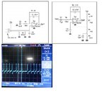
PIR1.jpg

Hi

I'm trying to design a PIR that has a range of 10m .Design i used for that is above . When i to probe at output of second stage amplifier, a noise with 0.5Hz is seen which is causing false detection .I've tried to reduce the range to 5m but the noise presence is still there . i just removed the PIR and checked the output it was clean. Please help me to solve this .

Thankzz
 

Hi,

It should work.

Some thoughts:
* what power supply do you use. Try a battery to see if it changes something.
* you are amplifying AC only. you use single power supply and your first input is GND referenced. Try to lift the input signal at least 100mV (max VCC/2), then the output can swing to both sides. See what happens.
* use proper bypassing/filtering of power supply lines. Both: bulk electrolytics and high speed ceramics.
* what 10uF capacitors do you use (dielectric)? You may try film capacitors to see if that helps somehow.

Klaus
 

    V

    Points: 2
    Helpful Answer Positive Rating
Hi,

These noises are only visible occasionally. some days these noises are not visible. I've seen these noises appear suddenly and disappear too.

1. I'm using a DC power supply unit, also tried 3.3V from other boards.
2.During detection i get output swing in both direction
3.I'm using ceramic capacitors.

I'll check when the noise is visible again with your recommendations

Thanks
Rohith
 

The signal looks too periodic to be caused by thermal fluctuations. Either it's blinking IR source or an electrical problem inside your circuit. You seem to have excluded the former by shielding the sensor.

I see that the PIR sensor is supplied by the common VCC source. You might see relaxation oscillations brought up by the very high signal gain and unwanted feedback. Try with additional stabilization and filtering of the PIR supply voltage.
 
Hi,

I've tried using a battery to power the Circuit. But there is still this noise

Thanks
Rohith
 

Hi,

did you try my second recommendation of post#2? "lift input voltage of first stage"..

Klaus
 

Is the resistor divider from source to ground is enough

- - - Updated - - -

What is relaxation oscillation? What kind of stabilisation circuit do you recommend?
 

When i to probe at output of second stage amplifier, a noise with 0.5Hz is seen which is causing false detection

Just to check:

Is that failure occurring just after probing the output with the oscilloscope ?
Did you try see the waveform with another instrument, but powered with battery instead from mains ?
 

These things were tried

- - - Updated - - -

Lets try that

- - - Updated - - -

"I see that the PIR sensor is supplied by the common VCC source. You might see relaxation oscillations brought up by the very high signal gain and unwanted feedback. Try with additional stabilization and filtering of the PIR supply voltage."

What is relaxation oscillation? Do you have any recommendations on additional stabilisation for power supply.
 

I suggested a filter in my previous post. If it changes the noise pattern somehow, you can proceed on that point. Otherwise it's no supply coupled interference.

I'm presuming you have a low impedance ground through the circuit. If the components are e.g. plugged into a test board, everything can go wrong.

https://en.wikipedia.org/wiki/Relaxation_oscillator, see second paragraph
 

The schematics appear to be copied from the ST app note
for the TSU101 in pyroelectric sensor applications

https://www.st.com/resource/en/application_note/dm00096551.pdf

Now in this app note regarding the second stage it says that
the low frequency cutoff is 0.6Hz, suspiciously close to the
waveform shown. Perhaps this pole is enabling a LF oscillator.
Perhaps it involves coupling between the stages. Might try
electrically separating them, and try changing the LF pole
component values in that 2nd stage to see if this moves
the frequency. Also if the comparator stage in the app note
is present (it is not shown in this thread) might test whether
switching noise injection is the stimulus that the LF pole
and gain turns into oscillation.
 
Also if the comparator stage in the app note is present (it is not shown in this thread) might test whether
switching noise injection is the stimulus that the LF pole and gain turns into oscillation.
It would be helpful to see the full picture. At worst case the comparator is driving a load with a considerable current consumption, e.g. a LED or a relays. Parasitic feedback can happen either through insufficiently filtered power supply or ground voltage drop.
 

Hi All ,

When i reduced the gain of first stage to 50 and doubling the gain on second stage(to compensate the range), noise is not visible now .Then i reintroduced previous gain the noise is visible .Anyone knows whats happening around.:thinker:

Thanks alot,
Rohith
 

Hi,

Don´t change two or more items the same time.

* Change the first stage and see if the first stage causes the problem
* Change the second stage and see if the second stage causes the problem

Klaus
 

If the problem is self oscillation as suggested by dick_freebird and me, it most likely can't be assigned to a specific stage because parasitic overall feedback is the reason. Arbitrary changes might stop the unwanted signal but possibly not reliably.
 

Status
Not open for further replies.

Part and Inventory Search

Welcome to EDABoard.com

Sponsor

Back
Top