Continue to Site

Welcome to EDAboard.com

Welcome to our site! EDAboard.com is an international Electronics Discussion Forum focused on EDA software, circuits, schematics, books, theory, papers, asic, pld, 8051, DSP, Network, RF, Analog Design, PCB, Service Manuals... and a whole lot more! To participate you need to register. Registration is free. Click here to register now.

[PIC] CCS PIC with SPI communication

Status
Not open for further replies.

nagkiller

Full Member level 4
Full Member level 4
Joined
Jul 9, 2009
Messages
238
Helped
37
Reputation
74
Reaction score
37
Trophy points
1,308
Location
Brazil
Visit site
Activity points
2,706
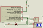
Hello.

I'm trying to write some values in eeprom 25AA160, but without success.

spi teste.png

Here is the code:

Code:
#include <16F1827.h>
#FUSES NOMCLR, NOBROWNOUT, NOFCMEN, NOSTVREN, NOLVP, NOIESO
#use delay(internal=4MHz)
#use spi (MASTER, CLK=PIN_B1, DO=PIN_B3, DI=PIN_B2, BAUD=1000000, MODE=0, BITS=8, STREAM=PIC)

#define CS     PIN_B4
#define LED    PIN_B7
// Instruction SET of 25AA160
#define READ   0B00000011  // Read data from memory array beginning at selected address
#define WRITE  0B00000010  // Write data to memory array beginning at selected address
#define WRDI   0B00000100  // Reset the write enable latch (disable write operations)
#define WREN   0B00000110  // Set the write enable latch (enable write operations)
#define RDSR   0B00000101  // Read Status register
#define WRSR   0B00000001  // Write Status register 

void main()
{
   output_high(CS);
   delay_ms(100);
   output_low(CS);
   spi_xfer(WREN);
   output_high(CS);
   output_low(CS);
   spi_xfer(WRITE);
   spi_xfer(0xF7F0);
   output_high(CS);
   delay_ms(100);
   for(;;)     
   {      
      delay_ms(100);
      output_toggle(LED);  
   }
}

Debug window:

debug.png

Could you tell me what is wrong???

10x
 

Hi,

I know nothing about your microcontroller i just see what is in your given schematic..

SDO1 --> MOSI (seems to be correct)
SDI1 --> SCK (please check)
SCK1 --> !SS (please check)
?? --> MISO (please check)

I can't even see how your program works.
I see you process CS line and i see adddress to be sent, but I can't find any data to be sent.

And I'm missing the compleate read of the sent data to verify the data transfer..

It seems you have a virtual scope tocheck SPI signals. Where is the output (screen)?

Klaus
 

At least you flipped DI and DO, so the code can't work. Master DO must connect to slave DI and vice versa.

Presume the #use spi statement calls software SPI as it doesn't use the dedicated SPI pins. This should work, for highest performance you better choose SPI hardware interface.

Personally I don't like the "use spi" directives, the software interface is "too clever" (respectively too stupid) for usual SPI purposes in my view.
 

I tried using:

SPI Master to Slave

MISO MISO
MOSI MOSI
SCK SCK
EN CS

or

SPI Master to Slave

MISO MOSI
MOSI MISO
SCK SCK
EN CS

....

I have changed the directive to "#use spi (MASTER, SPI1, ENABLE=PIN_B3, MODE=0, BITS=8, STREAM=PIC)", using the default hardware SPI, but not has effect.

Code:
#include <16F1827.h>
#FUSES NOMCLR, NOBROWNOUT, NOFCMEN, NOSTVREN, NOLVP, NOIESO
#use delay(internal=4MHz)
#use spi (MASTER, SPI1, ENABLE=PIN_B3, MODE=0, BITS=8, STREAM=PIC)
#define LED    PIN_B7
#define READ   0B00000011  // Read data from memory array beginning at selected address
#define WRITE  0B00000010  // Write data to memory array beginning at selected address
#define WRDI   0B00000100  // Reset the write enable latch (disable write operations)
#define WREN   0B00000110  // Set the write enable latch (enable write operations)
#define RDSR   0B00000101  // Read Status register
#define WRSR   0B00000001  // Write Status register 
void main()
{
   delay_ms(100);
   spi_xfer(WREN);
   spi_xfer(WRITE);
   spi_xfer(0x01, 0x01);
   delay_ms(100);
   for(;;)     
   {      
      delay_ms(100);
      output_toggle(LED);  
   }
}

What is the suggestion for layout and a simple source code to just write the value 0x01 at address 0x01 of the eeprom?

10x.
 
Last edited:

I´m using this MISO - MISO and MOSI - MOSI, but is not writing.

The software is invalid, i guess.

Would you like something simple ...

To understand the protocol.

10x.
 

MISO --> MISO
MOSI --> MOSI

Don't understand this.
MOSI net (master-out, slave in) connects µC DO and EEPROM DI
MISO net (master-in, slave out) connects µC DI and EEPROM DO
 

Hi,

Don't understand this.

I like the naming "MISO" and "MOSI".
And I´d be glad if all SPI device manufacturers use this naming.

With MISO you can draw a schematic and a signal keeps it´s name independent if it connects to a slave or a master.

****
In opposite there is UART naming "RxD" and "TxD". I allways find it difficult to name this signal in a schematic. At the master you should name this signal "TxD" but at the slave you should name the same signal "RxD".
Therefore in my designs I often use the the name "M2S" (Master_to_slave = Master_TxD = Receiver_RxD) or "S2M". This prevents me from beeing confused by my own signal naming.

Klaus
 

Personally I don't like the "use spi" directives, the software interface is "too clever" (respectively too stupid) for usual SPI purposes in my view.

I agree with that opinion, particularly if there is enough program memory available, and core usage is not an issue. In having two or more SPI devices with certain variations, it is possible to customize the interface in order to share the same routine therefore allowing access to different peripherals. Another advantage of using a software-based SPI interface is in the case of migrating to another core/family with no built in support for SPI on chip.
 

So could you tell me how to proceed?

I made a search on the Web for ready-to-use codes by using the criteria "C+library+SPI.H", and it is odd that did not result in so useful websites. The only place where it was possible to quickly find some libraries with bit handshaking it was exactly on the Microchip's website. Even if these codes were written for other family cores of that manufacturer or even other compilers, porting them to your application will be not difficult - even if you had to write by hand it would be quite straighfoward as the SPI protocol is something very simple. Here you can find a sample with which could make a try: https://www.microchip.com/forums/m729449.aspx .
 

Now its works!!!

Using driver from CCS Driver folder.

Code:
#include <16F1827.h>
#FUSES NOMCLR, NOBROWNOUT, NOFCMEN, NOSTVREN, NOLVP, NOIESO
#use delay(internal=4MHz)

#ifndef EEPROM_SELECT

#define EEPROM_SELECT PIN_B3
#define EEPROM_CLK    PIN_B4
#define EEPROM_DI     PIN_B2
#define EEPROM_DO     PIN_B1

#endif

#define LED    PIN_B7
#define EEPROM_ADDRESS long int
#define EEPROM_SIZE    2048

void init_ext_eeprom()
{
   output_high(EEPROM_SELECT);
   output_low(EEPROM_DI);
   output_low(EEPROM_CLK);
}

BOOLEAN ext_eeprom_ready()
{
   BYTE cmd[1], i, data;

   cmd[0] = 0x05;                  //rdsr opcode

   output_low(EEPROM_SELECT);

   for(i=1; i<=8; ++i) {
      output_bit(EEPROM_DI, shift_left(cmd,1,0));
      output_high(EEPROM_CLK);   //data latches
      output_low(EEPROM_CLK);      //back to idle
   }

   for(i=1; i<=8; ++i) {
        output_high(EEPROM_CLK);   //data latches
        shift_left(&data,1,input(EEPROM_DO));
        output_low(EEPROM_CLK);  //back to idle
   }
   output_high(EEPROM_SELECT);
   return !bit_test(data, 0);
}
void write_ext_eeprom(EEPROM_ADDRESS address, BYTE data)
{
   BYTE cmd[4];
   BYTE i;
   BYTE wren;
   wren=0x06;
   cmd[0]=data;
   cmd[1]=address;
   cmd[2]=(address>>8);
   cmd[3]=0x02;

   // Wait until the eeprom is done with a previous write
   while(!ext_eeprom_ready());

   output_low(EEPROM_SELECT);
   for(i=0; i<8; ++i)
   {
      output_bit(EEPROM_DI, shift_left(&wren,1,0));
      output_high(EEPROM_CLK);
      output_low(EEPROM_CLK);
   }
   output_high(EEPROM_SELECT);
   output_low(EEPROM_SELECT);
   for(i=0; i<32; ++i)
   {
      output_bit(EEPROM_DI, shift_left(cmd,4,0));
      output_high(EEPROM_CLK);
      output_low(EEPROM_CLK);
   }
   output_high(EEPROM_SELECT);
}
BYTE read_ext_eeprom(EEPROM_ADDRESS address)
{
   BYTE cmd[3];
   BYTE i,data;
   cmd[0]=address;
   cmd[1]=(address>>8);
   cmd[2]=0x03;

   // Wait until the eeprom is done with a previous write
   while(!ext_eeprom_ready());

   output_low(EEPROM_SELECT);
   for(i=0; i<24; ++i)
   {
      output_bit(EEPROM_DI, shift_left(cmd,3,0));
      output_high(EEPROM_CLK);
      output_low(EEPROM_CLK);
   }
   for(i=0; i<8; ++i)
   {
      shift_left(&data,1,input(EEPROM_DO));
      output_high(EEPROM_CLK);
      output_low(EEPROM_CLK);
   }
   output_high(EEPROM_SELECT);
   return(data);
}
void main()
{
   delay_ms(100);
   init_ext_eeprom();
   for(long int i = 0; i < EEPROM_SIZE; i++)
   {      
      write_ext_eeprom(i, 0x30); // Fill the 0s
      delay_ms(1);
   }
   for(;;)     
   {      
      delay_ms(100);
      output_toggle(LED);  
   }
}


sch.png
 

Status
Not open for further replies.

Similar threads

Part and Inventory Search

Welcome to EDABoard.com

Sponsor

Back
Top