Continue to Site

Welcome to EDAboard.com

Welcome to our site! EDAboard.com is an international Electronics Discussion Forum focused on EDA software, circuits, schematics, books, theory, papers, asic, pld, 8051, DSP, Network, RF, Analog Design, PCB, Service Manuals... and a whole lot more! To participate you need to register. Registration is free. Click here to register now.

Circuit not simulating buck converter

Status
Not open for further replies.

RITESH KAKKAR

Banned
Full Member level 5
Joined
Jul 6, 2010
Messages
263
Helped
7
Reputation
14
Reaction score
7
Trophy points
1,298
Location
INDIA
Visit site
Activity points
0

Attachments

  • aaaaaa.jpg
    aaaaaa.jpg
    382.5 KB · Views: 211

Pick a MOSFET type, the generic device can give strange results.
Label your nodes so we know what we are looking at (as shown in the video).
Post your .asc file (as a .txt file if necessary).
 

...and select appropriate scale for probing the output; Your "gate driver" generate a square wave with 25us Ton time, hence computing simulation from T=0us to 500us but the graph displays result up to 5,000us ( 5ms ).

- - - Updated - - -

It is not clear if the V1 reference is really connected to the GND.
I would expect an error message from simulator.
 

Pick a MOSFET type, the generic device can give strange results.
Label your nodes so we know what we are looking at (as shown in the video).
Post your .asc file (as a .txt file if necessary).
...and select appropriate scale for probing the output; Your "gate driver" generate a square wave with 25us Ton time, hence computing simulation from T=0us to 500us but the graph displays result up to 5,000us ( 5ms ).

- - - Updated - - -

It is not clear if the V1 reference is really connected to the GND.
I would expect an error message from simulator.

OK,i am sending file have
 

Attachments

  • buck.rar
    614 bytes · Views: 168

You did withhold that the simulation shows errors. It's due to incorrect parameter statements. (blue text in post#1).

You are writing text comments "pram" instead of Spice directives ".param". Please correct.

crutschow advised you to use a real transistor model instead of the generic NMOS type.
 
OK, sir i have done it.

it is showing transient output with 12V not 5V why?

showing error
Questionable use of curly braces in "v2 n002 n001 pulse(0 12 0 1n 1n {d*ts} {ts} 50)"
Error: undefined symbol in: "[d]*ts"
Questionable use of curly braces in "v2 n002 n001 pulse(0 12 0 1n 1n (d*ts) {ts} 50)"
Error: undefined symbol in: "[ts]"
Circuit: * C:\Program Files (x86)\LTC\LTspiceIV\buck.asc

Error on line 8 : v2 n002 n001 pulse(0 12 0 1n 1n (d*ts) (ts) 50)
Unknown parameter "d*ts"
Direct Newton iteration for .op point succeeded.

Date: Fri Jun 24 13:22:06 2016
Total elapsed time: 0.118 seconds.
tnom = 27
temp = 27
method = modified trap
totiter = 2714
traniter = 2709
tranpoints = 1226
accept = 1184
rejected = 42
matrix size = 11
fillins = 4
solver = Normal
Matrix Compiler1: 754 bytes object code size 0.3/0.3/[0.2]
Matrix Compiler2: off [0.2]/0.3/0.4
 

Attachments

  • aaa.jpg
    aaa.jpg
    332 KB · Views: 203
Last edited by a moderator:

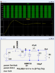
Here's is your circuit working.
I changed pram to .param and made it a Spice directive, not a comment (which is ignored by the program).
I used a real transistor model, not the generic for M1, as I previously suggested you do.
The output settles to about 5.6V.
It does not go th the theoretical 6V for a 50% duty-cycle due to loses in M1.

Buck.PNG

View attachment buck2.txt
 
made it a Spice directive, not a comment (which is ignored by the program).

Hello,
What is spice directory and while simulation the heading was showing newton rapson formula something like that which i studied in CBNST what is the use of it?
 

made it a Spice directive, not a comment (which is ignored by the program).
What is spice directory and while simulation the heading was showing newton rapson formula something like that which i studied in CBNST what is the use of it?

directive ≠ directory

I seriously recommend that you study a bit more the syntax and functionalities of this tool before proceeding with your simulation
 

how to remove transient error at starting
Which transient error? crutschow's simulation has no transient error, mine neither.

You didn't yet post a valid simulation file, don't know which circuit are you simulating right now?
 

Status
Not open for further replies.

Similar threads

Part and Inventory Search

Welcome to EDABoard.com

Sponsor

Back
Top