bowman1710
Full Member level 3

- Joined
- Nov 8, 2014
- Messages
- 183
- Helped
- 6
- Reputation
- 12
- Reaction score
- 6
- Trophy points
- 18
- Activity points
- 1,604
Hi Guys,
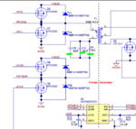
I'm looking at a design from TI, I noticed that they have used a cap and resistor on the transformer primary side, to eradicate any DC offset seen by the transformer.

Documents
https://www.ti.com/tool/PMP4435#Technical Documents
Schematic
https://www.ti.com/lit/df/tidrhw3/tidrhw3.pdf
My question is, the resistor is rated to 1/4W, with the currents seen on the primary, how can you have the resistor rated so low in power? Also whats the best way for calculating the optimum values for this?
Cheers
I'm looking at a design from TI, I noticed that they have used a cap and resistor on the transformer primary side, to eradicate any DC offset seen by the transformer.

Documents
https://www.ti.com/tool/PMP4435#Technical Documents
Schematic
https://www.ti.com/lit/df/tidrhw3/tidrhw3.pdf
My question is, the resistor is rated to 1/4W, with the currents seen on the primary, how can you have the resistor rated so low in power? Also whats the best way for calculating the optimum values for this?
Cheers


