Continue to Site

Welcome to EDAboard.com

Welcome to our site! EDAboard.com is an international Electronics Discussion Forum focused on EDA software, circuits, schematics, books, theory, papers, asic, pld, 8051, DSP, Network, RF, Analog Design, PCB, Service Manuals... and a whole lot more! To participate you need to register. Registration is free. Click here to register now.

MAX232/MAX3232 heating up.

Status
Not open for further replies.

uart_rx_tx

Junior Member level 3
Joined
Feb 6, 2016
Messages
27
Helped
0
Reputation
0
Reaction score
0
Trophy points
1
Activity points
384
Dear Friends,

I am using a MAX232 to convert RS232 level to UART TTL Level. It is between a Sensor and a Arduino MEGA2560. I have already tried 56K and 120K baud-rates...

Problem is that sometimes it works, even for hours without any problems and it remains cool! But if I decide to reset the power, it might not work and it starts heating up. If I let it to cool down for a while, there is a good chance it will work the next time.

I have used 4 of them from different batches, and the result is the same.

0. I am using the standard max232 circuit and I am sure I am using it correctly, because the circuit works most of the times.

1. I am using plastic film capacitors which are non-polarized. I think the cap type is not important....

2. I am using the recommended values for the capacitors, I have also used higher suggested values to no avail!

3. Supply voltage is a clean, non floating, derived by an LM7805 adequately bypassed.

4. I am only using one of the RX/TX, I/O. The others are left unconnected. One part of me wants to believe that they are floating, but I have various RS232/TTL converters and after checking their PCB I have found out that they are all left unconnected... They are not even connected to the ground plane. So why don't they float?

5. I am sure it is not software related, because ordinary RS232 to TTL converters work without any problem.

6. This even happens when the connection to the sensor is disconnected.

7. I don't know if the cable I am using to connect the Sensor to the MAX is contributing to this or not!

8. Some people have mentioned Latchup and ESD can contribute this.

9. Some people have:

a. used a resistor in series with the Vcc line to fix it. How can that fix this? And how should I choose the correct value for that?

b. someone has suggested: Between the DB9 shield to board's GND connect via Ferrite bead parallel 1000pF/2kV 0805 capacitor. ... how does this work?

c. Some people have fixed this by adding resistor to RX/TX lines. Where should I put these resistors? and what should be the value? and How this solve the problems?

d. Someone has fixed this by adding a couple .1uf ceramic capacitors for decoupling, in addition to the suggested ones.

10. Something crazy. I changed my circuit to MAX3232, according to its datasheet, and with correct capacitor size, and this happened again.

11. I am using a common ground between all of the connections.

12. I don't have a oscilloscope to check this. But when it doesn't work, the voltages drop to something like 1V on Rx or TX... I don't remember !

13. I don't know if the sequence of turning on the MAX232/Arduino and Sensor is an important factor. I'd be more than grateful if someone could tell me if it is an important factor.

14. I am using a Dorji RF transmitter very near to this MAX232, I don't know if something related to picking up RF signal by the max232 is the culprit or not!

15. Should the DB9 chassis be grounded?

16. someone has mentioned: This is most interesting. I have reproduced the fault on three chips now. Just to be clear, this is pin 2 to ground. Something else i noted, when the chip heats up, removing power and then repowering has to be done after it cools otherwise it heats again Is it possible that the ultra low ESR nature of the plastic film caps that I am using is the culprit? Is it even related? please forgive my ignorance.


What is the correct way to make this circuit bullet proof?!!? including a resistor? connecting all the unused inputs to gnd plane? I am trying to make the schematics finalized in Altium designer. So I'd be grateful to know what you electronics engineers
are suggesting.

Thank you a million times in advance.

:bang::bang:
:-D
 

Is this happening with any kind of modules connected there ? I mean, did you notice that failure occurring just at the same external interconnection, or any others ?
 
I am using a MAX232 to convert RS232 level to UART TTL Level. It is between a Sensor and a Arduino MEGA2560. I have already tried 56K and 120K baud-rates...

What exactly is this Sensor? Please be specific.

Can you provide the datasheet or user manual for this Sensor?

A schematic of the connections between the Arduino Mega2560, MAX232 and the Sensor would also be helpful.


BigDog
 
Hi,

Datasheet says:
9.3.2 RS232 Driver
Two drivers interface standard logic level to RS232 levels. Internal pull up resistors on TIN inputs ensures a high
input when the line is high impedance.
9.3.3 RS232 Receiver
Two receivers interface RS232 levels to standard logic levels. An open input will result in a high output on ROUT.

Please show us the complete datasheet including all connections and sensir and supply and so on.
And the PCB layout...or at least a photo of your circuit.

Klaus
 
Is this happening with any kind of modules connected there ? I mean, did you notice that failure occurring just at the same external interconnection, or any others ?

Thank you for replying to my question.

I only had this specific sensor. I don't have any other RS232 sensor to test!

About the RF transmitter, I must say that I haven't test it without it so I am not sure.

The ordinary RS232 to UART TTL converters that are readily available are working fine with either!

- - - Updated - - -

What exactly is this Sensor? Please be specific.

Can you provide the datasheet or user manual for this Sensor?

A schematic of the connections between the Arduino Mega2560, MAX232 and the Sensor would also be helpful.

BigDog

Thank you for replying to my question.

The sensor is 3DM-GX1®

Datasheet

Manual

Documentation
 

3. Supply voltage is a clean, non floating, derived by an LM7805 adequately bypassed

Does the Vcc bus keeps the same voltage during the heating of the MAX232 ?
Is your primary power source adequately sized to the overall power consumption, board+shields ?

Are there other devices connected to the Arduino board ? As far as I know, the 3,3v regulator of the Mega2560 burns easily. Check if the MAX232 are supplied by this voltage, what could give us some indication of the problem, that I'm suspecting it is related to the power supply. Some time ago I replaced the SMD regulator of a board of a friend from the original SMD part to a TO-220 package, obviously wired and glued to the board.

6. This even happens when the connection to the sensor is disconnected

I've not noticed it before, so we can discard external connections as the probable cause.

14. I am using a Dorji RF transmitter very near to this MAX232

Does the unconnected pins of the IC are unconnected to any routed track ?
 

Hi,

Datasheet says:

Please show us the complete datasheet including all connections and sensir and supply and so on.
And the PCB layout...or at least a photo of your circuit.

Klaus

I haven't drawn the Schematics in Altium, and I don't have the PCB layout ready yet. I have only tested it on the breadboard so far which works correctly most of the times.

I have gone crazy tens of times to connect the connections from the scratch. So I am 99.99% sure that my connections are like the datasheet.

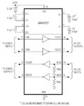
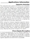
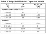
For max3232 I have used this:

max3232 schematic.jpg
max3232 capacitors.jpg
max3232 capacitors table.jpg

Since I am using 5v TTL, I am using the 2nd row values...

I have also tried these combinations:

C1 = 0.047uF and C2, C3, C4 = 0.67uF

and

C1 = 0.1uF and C2, C3, C4 = 0.67uF

I have used various combination of decoupling capacitors, single or in parallel! from suggested 0.1uF up to 10uF!

and you know what is very sad? The other cheap Chinese RS232 to TTL converter that I am using has the wrong capacitor values for 3.3V!!! and it is still working! it uses five 0.1uF capacitors which is not compatible with 5.0V according to the note which asks to increase C2, C3, C4 ... if one wants to increase C1.

I have connected the Pin14 to Male Connector number 3
I have connected the pin13 to Male Connector number 2

I have connected pin11 to Arduino TX1 (pin18)
I have connected pin12 to Arduino RX1 (pin19)

You can see some videos of the circuit here: https://www.edaboard.com/threads/350384/

Oh by the way the LED indicators are disconnected.... the circuit behavior is independent of the LED indicators above....

Again thank you very much for your time and consideration. I am deeply grateful that you are all committed to help me figure out whats wrong with my circuit. Without the doubt edaboard has one of the most amazing communities on the Internet.


ُ
 

I don't have the PCB layout ready yet. I have only tested it on the breadboard so far which works correctly most of the times.ُ

I'm sorry to say that fortunatelly this could explain that intermittent fail. The exposed wiring on this assembly act as excellent antennas, particularly if placed near to an RF emmiter so close as you mentioned
 

Does the Vcc bus keeps the same voltage during the heating of the MAX232 ?
Is your primary power source adequately sized to the overall power consumption, board+shields ?

I haven't measured the Vcc during the overheating.
I think it is adequately sized...

I tried to power up the MAX232/MAX3232 with Arduino Mega2560 5V output which only powers up a RF transmitter and several n-channel MOSFET's gate.

I have also tried to power it up with a dedicated LM7805 with a very big heat sink! Even without a heat sink it didn't even get warm!

I believe that Vcc is not the cause... it is very well bypassed...... and it is very clean. I have tested before, with an oscilloscope and it is steady!

Does the unconnected pins of the IC are unconnected to any routed track ?

I am not sure if I am getting what you are asking me. All of the unconnected pins of the IC are absolutely unconnected to anything. I am sure. I even clipped them on one of the ICs.

I'm sorry to say that fortunatelly this could explain that intermittent fail. The exposed wiring on this assembly acts as excellent antennas, particularly if exposed to an RF transmitter so close as you mentioned

I am very pleased to hear that :-D but I must say that I am reluctant to design the PCB without all the measures that I can take right now. Like this guy here, I want to take all the measures to make this circuit bullet proof.... I am a little anxious, because I have seen some people with overheating max232/max3232 on the PCB! There are abundant threads all over the internet...

So I really want to know what I can add to this circuit to preclude overheating problems....

I'd be thankful if you could share you thoughts.
 

I am not sure if I am getting what you are asking me. All of the unconnected pins of the IC are absolutely unconnected to anything. I am sure. I even clipped them on one of the ICs

Ok, I asked this before of being aware of your actual assembly, that is not at a PCB board.

Anyway, once the NC pins of the MAX232 are in a galvanic contact with the inner rails of the breadboard - which can absorb part of the surrounding RF emissions - I would recommend you bend them 90o in such a way that them do not contact anymore the breadboard. In addition, you could connect to GND all unconnected rails of the breadboard near to the IC, so that will work as a shielding grid.
 

Hi,

Capacitor values:
Are relatively uncritical. The table shows the minimal values..you could use bigger values.

but I must say that I am reluctant to design the PCB without all the measures that I can take right now. Like this guy here, I want to take all the measures to make this circuit bullet proof.... I am a little anxious, because I have seen some people with overheating max232/max3232 on the PCB! There are abundant threads all over the internet...
Millions of MAX232 circuits are running without problems.
Many circuits I develop run without previous measurements...just by keeping on the requrements of the datasheet...and with a good PCB layout.
Sometimes neasurements on breadboards are meaningless because they depend on the wiring...

Klaus
 

The normal cause of the Max232 heating up is due to one or more of its outputs being connected to another output. You say that your circuit is working, but do you use all of the outputs when you test it?
It cou;d be due to latch up, although I have not experienced it with the Max232. Ensure the inputs to the Max232 are disconnected when powering up.
 

Is it possible for you to move the transmitter a few feet away and see if problem goes away.
 

Is it possible for you to move the transmitter a few feet away and see if problem goes away.

Thank you veI moved it 3 feet away and it still happens.

- - - Updated - - -

The normal cause of the Max232 heating up is due to one or more of its outputs being connected to another output. You say that your circuit is working, but do you use all of the outputs when you test it?
It cou;d be due to latch up, although I have not experienced it with the Max232. Ensure the inputs to the Max232 are disconnected when powering up.

No I only use one from RX and one from TX.

The more I read on the internet, the more I am convinced that the symptoms are related to latch up! How can I stop latchup from happening?!

I cannot disconnect the inputs... but, what do you mean exactly?! To stop rs232 side?! Can I just turn off the rs232 sensor?

- - - Updated - - -

==============
==============
==============
==============
==============

1. Ok. I want to use the resistor in series with Vcc. I am thinking about drawing two traces to the max232.... one without any resistor, and one with a resistor, each one with a jumper!

In case I run into heating up problem I can disconnect the jumper from the resistor free trace and connect it t the trace with a resistor. At least this way I am not required to order another PCB!

I have read on the internet that this resistor has solved the problem for those who have tried it. But I don't understand how this is possible? I mean what is the mechanism?

How should I choose the correct resistor? Someone has mentioned that he has used 20 ohm! Is it enough?!

Do you have any specific recommendation about this approach? Or possibly you think that it is a bad idea?

2. About the unused pins: I can do several things:

a. clipping them? Lol

b. Connect them all to the gnd.

c. connect each RX to the other RX and each TX to the other TX? Something similar to piggybacking?? On another board, someone suggested this to another user.


Thank you again a million times!
 

This is a interesting thread about your latch-up problem. I like it because the person with the problem has a well laid out PCB and SMD components.

https://e2e.ti.com/support/interface/etc_interface/f/392/t/233847

A few ideas are talked about and then in the last post someone says he can repeat the problem every time.

"In my case I think I have found the scenario that causes the latch-up - every time the analog side RS232 pins of the chip are connected to a powered serial port (e.g. connecting a board with the MAX232 to a running PC's serial port) without power applied to it's power pins (i.e. the board not powered), once I apply +5V to the chip it immediately enters the latch-up condition. I have narrowed this to the TxD input - because it's driven with a negative voltage (negative idle voltage on RS232 line), the combination of rising VCC and negative input on TxD causes in my opinion the latch-up condition. This seems like a bug of these chips related to the silicon implementation."
 

Hi,

At least this way I am not required to order another PCB!

What a surprise! You have a PCB?
Can you show us?

What exact manufacturer and device number is the MAX232?

Klaus
 

These pins connected to the long wirings at the serial cable could exaplain that; acting such as antennas to get all sort of EMI. Perhaps adding external pull-up/down resistors as mentioned before could avoid or minimize the ocurence of this problem.

This seems like a bug of these chips related to the silicon implementation

Is this happening with MAX232 chips from different manufacturers ?
 

Hi,


What a surprise! You have a PCB?
Can you show us?

What exact manufacturer and device number is the MAX232?

Klaus

Hi Klaus,

I haven't ordered the PCB yet. I mean, instead of designing a PCB without a resistor in VCC line, I am going to design a PCB with two traces... one with a resistor and one without a resistor... Quote from my last post "At least this way I am not required to order another PCB!"

In sum, I don't have a PCB at this time!

One of them is MAX3232 from Maxim
Two of them are MAX232CPE from Maxim
The other two are MAX232 from Texas Instrument

And yes! Of course I've got them from a trusted vendor!
And yes again! Of course I have used the correct capacitor size for each of them!

- - - Updated - - -

This is a interesting thread about your latch-up problem. I like it because the person with the problem has a well laid out PCB and SMD components.

https://e2e.ti.com/support/interface/etc_interface/f/392/t/233847

A few ideas are talked about and then in the last post someone says he can repeat the problem every time.

Thank you very much for caring to do a research. It is not the last post... it is the last post on page 1.

Yes, I have seen that thread, but unfortunately there isn't any solution suggested by that guy.

Have you also seen the page page 2 and page 3?

There is also another similar thread, page 2, page 3

I am a beginner in electronics. So I am not understanding what they are talking about....! :blah:

- - - Updated - - -

These pins connected to the long wirings at the serial cable could exaplain that; acting such as antennas to get all sort of EMI. Perhaps adding external pull-up/down resistors as mentioned before could avoid or minimize the ocurence of this problem.


Is this happening with MAX232 chips from different manufacturers ?

Dear Andre,

Yes, this is happening with chips from different manufacturers.

Thank you, Yes, It is is very possible that your theory is right. But since it has happened to other people who used it on a PCB, I am trying to be cautious and preclude the possibility of ordering a new PCB .....!

Could you please tell me where to put the pull-up/down resistors? And what should the value of resistors be? A schematic is going to be very helpful for a beginner like me.
 

Hi,

from Maxim MAX3232 datasheet:
The transmitter inputs do not have pullup resistors.Connect unused inputs to GND or VCC.
This means: Don´t let them floating! This applies to PINs 10 and 11.

A zener across VCC and GND could help to avoid overvoltage and undervoltage, especially with low value VCC capacitors.

Klaus

- - - Updated - - -

ADDED:

Pullup value:
Datasheet says:
* Input leakage current max. = 1uA
* Input logic threshold igh = 2.4V (@5V VCC)

This means the pullup is between VCC and T_IN.
When T_in = 2.4V, then U_Rpullup = 2.6V

R = U / I = 2.6V / 1uA = 2.6MOhm.

But this is the minimum current = max pullup resistor.. without any other connection to T_IN (like a wire or a connector)

My recommendation: use 100k.

Klaus
 
Hi,

from Maxim MAX3232 datasheet:

This means: Don´t let them floating! This applies to PINs 10 and 11.

A zener across VCC and GND could help to avoid overvoltage and undervoltage, especially with low value VCC capacitors.

Klaus

- - - Updated - - -

ADDED:

Pullup value:
Datasheet says:
* Input leakage current max. = 1uA
* Input logic threshold igh = 2.4V (@5V VCC)

This means the pullup is between VCC and T_IN.
When T_in = 2.4V, then U_Rpullup = 2.6V

R = U / I = 2.6V / 1uA = 2.6MOhm.

But this is the minimum current = max pullup resistor.. without any other connection to T_IN (like a wire or a connector)

My recommendation: use 100k.

Klaus

Thank you very much Klaus.

Is it possible to provide a schematic?!

I am still deeply grateful from your help with the LED indicator with pulse stretching!
 

Status
Not open for further replies.

Similar threads

Part and Inventory Search

Welcome to EDABoard.com

Sponsor

Back
Top