Continue to Site

Welcome to EDAboard.com

Welcome to our site! EDAboard.com is an international Electronics Discussion Forum focused on EDA software, circuits, schematics, books, theory, papers, asic, pld, 8051, DSP, Network, RF, Analog Design, PCB, Service Manuals... and a whole lot more! To participate you need to register. Registration is free. Click here to register now.

frequency to voltage conversion

Status
Not open for further replies.

aliyesami

Full Member level 6
Full Member level 6
Joined
Jan 7, 2010
Messages
369
Helped
0
Reputation
0
Reaction score
0
Trophy points
1,296
Location
USA
Visit site
Activity points
4,190
whats the best option I have to convert frequencies between 5Khz - 15Khz into analog voltage signal varying between 1-3.3v ?
 

Are you converting sinewaves? Then you can create a high pass CR filter, and send it to a sample-and-hold. Then higher frequencies result in a higher DC voltage. (Put a resistor on the output of the S&H so it discharges the capacitor quickly.)

If it is not a sinewave input, then a one-shot and charge bucket can do the job.
 

Hi,

What do you mean with "best"?
Best precision, lowest part count, lowest cost, lowest effort or something else?

Specify: Voltage levels and signal waveform.

You could use an 8 pin microcontroller. Use a timer to measure the frequency (should be able with error below 0.1%. Depends on frequency range)
And generate a PWM. Control an analog switch connected to 3V3 and 0V...then add a low pass filter.

Should be very precise according: offset error, gain error and linearity.

Klaus
 
Last edited:

If it is not a sinewave input, then a one-shot and charge bucket can do the job.
its a square with 50% duty cycle 0-3.3v peak-to-peak.
I found these frequency to voltage converter chips on web, can you recommend me one?

- - - Updated - - -

Hi,

What do you mean with "best"?
Best precision, lowest part count, lowest cost, lowest effort or something else?
lowest effort with most precision

Specify: Voltage levels and signal waveform.
its a square wave with 50% duty cycle, 3.4 v peak to peak.

You could use an 8 pin microcontroller. Use a timer to measure the frequency (should be able with error below 0.1%. Depends on frequency range)
And generate a PWM. Control an analog switch connected to 3V3 and 0V...then add a low pass filter.
I am aware of this method but I cant use my micro as I am using all of its timers for other purposes.

I like these V-to-F chips , can I use these ?
 

Hi,

I like these V-to-F chips , can I use these ?
You ask about frequency --> voltage conversion.

V-F converters work the wrong direction. They convert voltage --> frequency. I don´t think you can use tham with low effort.

Klaus
 

Hi,

F-V converters are integrated circuits especially made for your demand.

Read the datasheets to find out about the erros and if this fits your needs.

Klaus
 

hi Klaus i am not that rich yet to afford custom made chips , isnt there a frequency to voltage chip that covers some general input frequency range ?
I talked to digikey people just now and they are saying i cant use FTV chips for my application since i have a digital input square wave .. is that true ?
I was thinking its a very common thing that i am attempting to do.

- - - Updated - - -

Most straightforward way is to trigger a monostable multivibrator and then integrate the output with an RC filter.

hi warspeed can you eleborate on this method , how it works? looks like this is my only option moving forward.
 

The standard 555 timer is only specified to work down to 4.5 volts.
However the cmos 7555 version is specified down to 2.0 volts.

R6 and C5 produce a dc output, but C5 can be changed if needed to make it either respond faster to changes, or give a smoother output with less ripple.
 

Hi,

hi Klaus i am not that rich yet to afford custom made chips , isnt there a frequency to voltage chip that covers some general input frequency range ?
I talked to digikey people just now and they are saying i cant use FTV chips for my application since i have a digital input square wave .. is that true ?
These are typical questions to be answered by the datasheet.
I don't have all datasheets in mind...so i have to read the datasheet...or even better: you read the datasheet.

--> I can't think of a reason now why they should not work with sqare wave. In opposite I'd say a square wave is a very reliable signal waveform. Datasheet will tell you.

2- how can i convert the PWM voltage output to pure DC ?
As said before: use a low pass filter.

First order( RC) is simple. To lower the ripple at 5kHz to 1% (of VCC) you need a corner frequency of about 50Hz. (Rule of thumb: 5kHz x 1%), but time constant tau is about 3ms.
If you need lower reaction time (tau) then consider a second order LPF, but with fc of about 300Hz.

To lower the remainig ripple fc should be lower, too.

Klaus
 

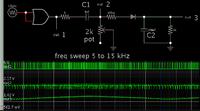
Here's a simple F-to-V converter. Positive transitions are turned into spikes by a series capacitor. Then feed through a diode to a simple sample-and-hold.


You'll need to amplify the output so it conforms to your specs.

You do not need the logic gate at the left. It turns the simulated sine sweep into square wave pulses. You state you already have a square wave input.
 

A simpler explanation is

1. Clamp the square wave to a fixed amplitude;
2. Assume there are no negative values; if yes, pass through a diode;
3. Differentiate the square wave so that you get fixed amplitude pulses (at twice the frequency);
4. Charge a capacitor (via a diode) that is also called sample and hold (see the previous post); mathematically it is called integration;
5. Allow the capacitor to lose charge (so that max value is kept only for some time)- limit the bandwidth.

That is what BadtheRad has done above. I have just put the same thing in a different language.
 

The 555 circuit above is a little interesting as the components connected to pin 7 do absolutely nothing to aid in the function of the circuit - is the circuit even correct?

- - - Updated - - -

The old XR2206 can e set up as a phase locked loop to give you F -> V

also the CMOS chip HEF4046 can be set as a F->V as it contains a PLL also...
 

for these super low frequencies, use a current source/capacitor ramp generator circuit. Start the ramp at the positive going zero crossing of the input sine wave, and reset the capacitor to 0 Volts at the negative going zero crossing. Save the peak ramp voltage value in a simple diode/hold capacitor and read off the voltage from that hold capacitor. It should be very accurate and linear.
 

Hi,

It should be very accurate and linear.
It will not be linear to f, but it will be about linear to 1/f.

But maybe a solution..

Klaus


hi Tony

this circuit uses 12V , i can only use 3.3v or 5V. can i modify this circuit for 3.3v or 5v ?

- - - Updated - - -

An XR4151 can do Both ways:
Frequency to Volts or Volts to Frequency.

the data sheet says it requires input signal of 5v , i have 3.3v signal .

- - - Updated - - -

I just realized i can always tap into my fan power supply which is 12v .
what do you think of this cicuit ?
https://www.ti.com/lit/an/snoa734b/snoa734b.pdf
 

Status
Not open for further replies.

Similar threads

Part and Inventory Search

Welcome to EDABoard.com

Sponsor

Back
Top