Continue to Site

Welcome to EDAboard.com

Welcome to our site! EDAboard.com is an international Electronics Discussion Forum focused on EDA software, circuits, schematics, books, theory, papers, asic, pld, 8051, DSP, Network, RF, Analog Design, PCB, Service Manuals... and a whole lot more! To participate you need to register. Registration is free. Click here to register now.

Ohm to Lux with Arduino Coding

Status
Not open for further replies.

TheRealArchi

Newbie level 3
Newbie level 3
Joined
Feb 8, 2016
Messages
3
Helped
0
Reputation
0
Reaction score
0
Trophy points
1
Visit site
Activity points
40
Light Restance: Ohm to Lux

Hello. I have a PhotoResistor of this model: Arduino KY-018 Photo resistor module.
It gives me values in Ohm but I need to convert it to Lux. I have no idea how to since there's no information on the product I bought..
I tested and it gave around 1050 Ohm when there's 0-10 lux.
 

Re: Light Restance: Ohm to Lux

You shine light on the photo resistor and its resistance drops. It is cheap Chinese junk so it does not have a detailed datasheet. I doubt its resistance will always be the same with a certain amount of light, it will probably get less sensitive as it ages. Some of my cheap Chinese solar garden lights used photo-resistors but they got sunburned and stopped working.

What do you want to convert? You feed it light and its resistance drops. You do not feed it resistance and expect it to produce light.
 
Re: Light Restance: Ohm to Lux

The ratio between resistance to light is certainly not-linear. The first thing you have to do is measure the full range of possible valuesof light (using a resolution as narrow as possible) and map the result into a table. After that you can review the results graphically to check whether the ratio is satisfactorily linear or if you will have to generate some non-linear function to represent the electric model of the component.
 
Re: Light Restance: Ohm to Lux

It's just that I have an Arduino coding and I want to show the Lux value on the LCD I use. But it's showing the resistance that drops the lighter is the room. I was thinking if there's a code or I just have to measure it's Resistance depending of the Light I give. Thanks for your response, now I'm sure I'll do what you said. :thumbsup:
 

Re: Light Restance: Ohm to Lux

if you are using an Arduino, why don't you use an I2C based light sensor, like the TSL2550?
 

Re: Light Restance: Ohm to Lux

I tested and it gave around 1050 Ohm when there's 0-10 lux

You're probably aware of that, even if you use a calibrated meter to gauge the scale, it doesn't mean that both meters ( yours vs. professional ) will exhibit the same result whatever the lighting. It occurs because your measurements are being done with a sensor which have its particular bandwidth response for different wavelength of the light.
 

Hello.
I have an Arduino KY-018 Photo resistor module. I have a code that displays the value the resistor gives.
I made few tests with the Value compared to Lux received. I found a 3rd degree polynomial that can help me convert the value it gives into lux.
Here are my tests:
Ohm Lux
1030 0
380 34
270 73
240 150
85 700
22 2000
12 5000​
Using Excel I found a 3rd degree polynomial that display more or less well the equation which is:
y = 66.861x3 - 539.46x2 + 1336.9x - 910​
where x = ohm and y = lux.
I tried to put this equation on my code but Arduino won't actually do the calculations and it simply replaces the result by a 0.
What code should I use ?
 

The function that you found seems apparently inconsistent with the table, once extrapolating R=0, the Light should be at least in the range of some thousands, but your formula gives 910, but negative (?).

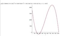
By using this online polynomial regression tool, I fould another result, which seems more reasonable for R=0:

y = -6.515451284·10-5 x3 + 1.003791607·10-1 x2 - 38.13560278 x + 3976.562716

You have to make some experiments in math, but the 3rd degree term sounds negligible.
 

You could make a table from your tests, and interpolate for the values beween the table values. Depending on how many testpoints you have in the table, this should give you as good a value you may get from a LDR.
 

Re: Light Restance: Ohm to Lux

By using this online polynomial regression tool, I fould another result, which seems more reasonable for R=0:

y = -6.515451284·10-5 x3 + 1.003791607·10-1 x2 - 38.13560278 x + 3976.562716

You have to make some experiments in math, but the 3rd degree term sounds negligible.

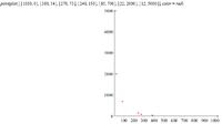
Indeed is awful. Watch:


Points:


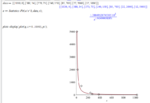
Looks like more a decreasing exponential..
 

There is someting strange with the data colected, due to the picture above do not match the values of the table. Even with another online tool available on the web, wolframalpha, resulted a formula with a strong error.
 

The data collected looks very nonlinear and may have other accuracy issues related to comparison to diffused Lambertian response or point sources when compared with the LUX meter.

I have used a Panasonic photo sensor part which is very linear on a log scale over 4 decades which is also CIE eye corrected,

I highly recommend you choose that part. https://www.digikey.com/product-detail/en/AMS302/255-2655-ND/2125641
ldr.jpg
See what I mean about your non-linear data?
 

Hi,

the current of a photo diode is very linear to lux.
All you need is a TIA.

Klaus
 

Most online tools perform regression based on Polynomial, logarithmic or exponential models exclusively, but none have been able to synthesize a representative formula of the sensor function with an acceptable error.

In fact, there may be some formula consisting of the combination of the above models, or perhaps even relatively simplest, such as a simple inversion e.g f(x) = K1 + K2/x, but apparently with this sensor the task will be more complicated .
 

@CataM, Nice results ! In fact there are some points far of the curve, but could be errors related to the measurement itself.

@Audioguru, I tried to find a formula for the dataset at that link, which has an option to build a formula with a logarithmic function, but applying the input scale to that formula, it returned a negative result at the end of the curve. Apparently there is some quite particular function that matches the response of this sensor, but the formula that CataM found above seems the most accurate so far.
 

Status
Not open for further replies.

Part and Inventory Search

Welcome to EDABoard.com

Sponsor

Back
Top