Continue to Site

Welcome to EDAboard.com

Welcome to our site! EDAboard.com is an international Electronics Discussion Forum focused on EDA software, circuits, schematics, books, theory, papers, asic, pld, 8051, DSP, Network, RF, Analog Design, PCB, Service Manuals... and a whole lot more! To participate you need to register. Registration is free. Click here to register now.

Short circuit protection in H-bridge

Status
Not open for further replies.

kushal nandanwar

Full Member level 3
Full Member level 3
Joined
Jun 9, 2013
Messages
177
Helped
6
Reputation
12
Reaction score
6
Trophy points
18
Visit site
Activity points
1,258
I my attached circuit I want to limit it to 3A.
can any one provide me circuit for it.
 

Attachments

  • Short_circuit.pdf
    4.9 KB · Views: 295

Hi Kushal,

If you mean at the power rail input to the bridge - just an idea, might not work or be suitable - how about using an op amp as an error amplifier driving a low rdson p channel as a high side gate (if that's how you say it) or a power BJT, using a very low value sense resistor in series with the MOSFET/BJT output/input to the bridge. Good and bad is that a 5 milliohm sense resistor only drops 15mV.

Could include a shutdown at or over 3A using a comparator instead of the error amplifier idea, but that senses something more sensible than 15mV, maybe using a 0.5 ohm sense resistor - but that would drop 1.5V and waste 4.5 Watts. If you use a 0.010 or a 0.005 sense resistor, or better a 100 milliohm (0.9 Watts and 300mV dropped) and amplify that voltage into a comparator.

I'd go with the PNP BJT version myself, as it's all I'd know how to try to make, driven by an NPN small BJT as I'd find it easier to implement regarding the op amp error amplifier controlling the current at 3A (hopefully), and you could still add a comparator to shutdown the line in over current situation using another NPN out of the comparator driving a PNP which could be used to pull the H-Bridge PNP gate low (i.e. high) - maybe?

Maybe hard to put together: a comparator that detects 3A and instead of shutting down triggers an error amplifier to limit current to the 3A value - not sure how to put that idea into practice without a lot of thinking, sorry.
 

A simple current-limit design uses two BJTs, but that requires about a 0.25Ω resistor in series with the power to the bridge.
If that's too large a resistor, then you need to go with a more complex circuit such as the comparator and transistor that d123 suggested.
What's your preference?
 

A simple current-limit design uses two BJTs, but that requires about a 0.25Ω resistor in series with the power to the bridge.
If that's too large a resistor, then you need to go with a more complex circuit such as the comparator and transistor that d123 suggested.
What's your preference?

Assuming a loss of 750mV is acceptable, and there being no need for the complex idea, I'm upvoting the 2 BJT and 0.25 ohm idea and downvoting what I suggested. ...getting carried away with comparators and nearly forgetting the 7805 bypass and overcurrent circuit from a few months ago, again, thanks for help then.
 

Hi Kushal,

If you mean at the power rail input to the bridge - just an idea, might not work or be suitable - how about using an op amp as an error amplifier driving a low rdson p channel as a high side gate (if that's how you say it) or a power BJT, using a very low value sense resistor in series with the MOSFET/BJT output/input to the bridge. Good and bad is that a 5 milliohm sense resistor only drops 15mV.

Could include a shutdown at or over 3A using a comparator instead of the error amplifier idea, but that senses something more sensible than 15mV, maybe using a 0.5 ohm sense resistor - but that would drop 1.5V and waste 4.5 Watts. If you use a 0.010 or a 0.005 sense resistor, or better a 100 milliohm (0.9 Watts and 300mV dropped) and amplify that voltage into a comparator.

I'd go with the PNP BJT version myself, as it's all I'd know how to try to make, driven by an NPN small BJT as I'd find it easier to implement regarding the op amp error amplifier controlling the current at 3A (hopefully), and you could still add a comparator to shutdown the line in over current situation using another NPN out of the comparator driving a PNP which could be used to pull the H-Bridge PNP gate low (i.e. high) - maybe?

Maybe hard to put together: a comparator that detects 3A and instead of shutting down triggers an error amplifier to limit current to the 3A value - not sure how to put that idea into practice without a lot of thinking, sorry.

I have 3miliohm , 4miliohm and 8miliohm with me, can you provide reference circuit.

- - - Updated - - -

A simple current-limit design uses two BJTs, but that requires about a 0.25Ω resistor in series with the power to the bridge.
If that's too large a resistor, then you need to go with a more complex circuit such as the comparator and transistor that d123 suggested.
What's your preference?

can you provide reference circuit.

I have micro controller also on my board, I can also use it to stop PWM generation or turn off all MOSFET, but need a logic to sense 3A current.
 

Hi,

Look for
* current sense amplifiers,
* shunt monitors

Klaus
 

I have 3miliohm , 4miliohm and 8miliohm with me, can you provide reference circuit.

Simple method to measure current, referenced to the positive supply. A PNP transistor is operated in common base mode.

The 4 m-ohm shunt is placed at the top of the load.


Simple method to measure current, referenced to the positive supply. A PNP transistor is operated in common base mode.

The 4 m-ohm shunt is placed at the top of the load.

The polarity on the PNP is incorrect for it to conduct (base and emitter need to be reversed) but, even if it did, with that value of shunt resistance the minimum short circuit current is about 175A(!) since the transistor requires about 0.7V Vbe to turn on.
For a 3A limit the sense resistor needs to be about 0.25Ω.
 
Last edited:

The polarity on the PNP is incorrect for it to conduct (base and emitter need to be reversed) but, even if it did, with that value of shunt resistance the minimum short circuit current is about 175A(!) since the transistor requires about 0.7V Vbe to turn on.
For a 3A limit the sense resistor needs to be about 0.25

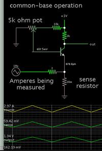
Common base operation has the signal applied to the emitter leg. As Ampere flow creates a voltage across the shunt resistor, it changes net B-E voltage.

As you say it will be easier if the shunt resistance is higher. I tried a couple of adjustments and stopped when the output was at a midway level.

To make it work, requires careful adjusting of bias. Eventually it should be possible to get zero output with zero input. (Output is referenced to supply+.) It should be possible to obtain linear response.
 

I'm puzzled as to how it can work.
As the current increases the emitter voltage becomes more negative (less positive) when tends to shut the transistor off.
Or is that what you intended, that the transistor is normally ON and turns off as the current increases.
If so, that circuit will be very sensitive to the base-emitter voltage and any change in temperature.
 

This is the NPN version which I tested with hardware. The emitter leg consists of a few inches of wire. I run current through it, creating a voltage drop. (That is the only wire that carries heavy current.) The voltage drop varies 0-60 mV. The common-base amplifier applies voltage gain. I take output at the collector leg.

It gives 1 or 2 volts swing, while I turn the power supply from 0 to 3.5 A.


Bias must be carefully adjusted. Some leakage appears unavoidable. I find I cannot get 0V output with zero current input.
 

Hi,

voltage drop varies 0-60 mV.
while I turn the power supply from 0 to 3.5 A.
Means every mV represents about 50mA.
VBE drifts with about -2mA per °C. Expect a change in current reading of about 100mA every °C temperature change of the bjt.

Klaus
 

Hi Kushal,

Have you got a circuit to work for this yet?

Do you have any op amps? If you do, what are they, please? You have 3, 4 and 8 milliohm... do you also have higher values like 0.2 to 0.5 ohm and if need be up to 1 ohm?

To turn the bridge off at 3A:
If you put a series resistor from V+ to the bridge, like the 0.25 that crutschow said, then at 3A it will have a voltage of about 750mV (and pd 2.25W). A difference amplifier with the inputs across the resistor can be used to feed a comparator that is set to go high at about 750mV, powered on a 5V rail, the comparator will output a logic level signal, unless you need 3.3V, then if you have op amps you can power from 2.7 - 5.5V, then that will give an output of about 3.2V.

If you use the 8 milliohm resistor, I'd amplify the difference output by 1000 - might make it imprecise. If amplify by 100 then 24mV would be 240mV, not much room for manouevre there, but it could work fine if you have a stable 5V or 3.3V line for the comparator and resistor ladder divider.

I know you're not supposed to, but I use normal op amps to make comparators, because comparators are often open collector output, which can be a nuisance to interface to positive triggered devices.

I think the two transistor version is simple and low parts to implement, but could be harder to get a precise response at 3A.
 

I'm puzzled as to how it can work.
As the current increases the emitter voltage becomes more negative (less positive) when tends to shut the transistor off.
Or is that what you intended, that the transistor is normally ON and turns off as the current increases.

I admit the schematic made me unsure myself, the longer I looked at it (post #13).

I tried more experiments with a real circuit. At idle, I bias the transistor so it turns on, just enough to bring my meter reading near zero.

Then I run current through the emitter leg by itself. This causes its voltage to rise a few mV.

In effect reducing B-E voltage.

The transistor turns off. The meter reading goes up.

If so, that circuit will be very sensitive to the base-emitter voltage and any change in temperature.

Expect a change in current reading of about 100mA every °C temperature change of the bjt.

Klaus

Yes, I tried holding the transistor between my fingers. Meter reading drops 10 percent. Then I release it, and the reading slowly rises.

It will improve temperature stability if the shunt were greater resistance.
 

Status
Not open for further replies.

Similar threads

Part and Inventory Search

Welcome to EDABoard.com

Sponsor

Back
Top