Continue to Site

Welcome to EDAboard.com

Welcome to our site! EDAboard.com is an international Electronics Discussion Forum focused on EDA software, circuits, schematics, books, theory, papers, asic, pld, 8051, DSP, Network, RF, Analog Design, PCB, Service Manuals... and a whole lot more! To participate you need to register. Registration is free. Click here to register now.

[AVR] Display Quality Issues for 120x12 Led Sign Board

Status
Not open for further replies.

codename25

Member level 3
Member level 3
Joined
Jan 15, 2015
Messages
65
Helped
0
Reputation
0
Reaction score
0
Trophy points
6
Visit site
Activity points
555
Hi,
I had developed an led sign board (120X12 it is quite lengthy) and its length is around 3 meters. I am using 74HC595 shift register for the columns and 12 lines from microcontroller directly to the rows. The problem I'm facing is my code is designed like the row is activated only after sending all the data to the shift register. Since the whole display is lengthy it takes much time for sending whole data to shift register which means at this time nothing is displayed. This is making the display very dull and flickering. I had even set the delay time to 0.07ms for row in high but this is making the display dimmer. If set delay to higher values the display is flickering largely. Is there any solution for this. Thanks in advance.

Eg: Time taken to send whole data to shift register: 10ms

row is activated time: 10ms

Here, in 20ms, the display is idle half of the time. This is making the display dull and flickering.
 

If your registers are serially connected to both rows and columns, can't they be latched simultaneously so there is no dead time.

1440 LEDs and what is your clock rate for 10ms ? 142kHz?

try faster.
 

Hi,
Thanks for the reply. Sorry, i have connected the latch (output enable pin13) to low for all the shift registers also i mentioned that row is connected to microcontroller columns are connected to shift registers. The 10ms is just an example it is not an actual value used. Thank you.

Another thing i wat to add is if im going with a serial connection for both row and column, it would take much more time for sending the data ( now the data to the row and column is to be sent) which make it much more dull and flickering.
 
Last edited:

What kind of microcontroller are you using? Does it have built-in SPI hardware? If so, you can usually clock bits out at the CPU clock frequency and it is very simple. For something like an Arduino, this could be up to 16MHz. That said, 16MHz is pretty fast (and the shift register you are using could handle it), but your wiring probably won't allow for that kind of speed. At say 1MHz data rate, you should be able to shift out the 120 bits for a row in 120uS. Then turn on the row to display. Now shift out the next row, and so on. That should be fast enough.

A bigger problem, I think, is the amount of multiplexing you are doing. You are asking your microcontroller I/O pins to drive from 0 up to 120 LEDs at a time, IN PARALLEL. Even the low-power 5mm LEDs need around 5mA-10mA to be brightly illuminated. Worst case, your row driver (I/O line from the micro in your case?) needs to drive 120x10mA 1.2 AMPS. Using a single resistor to limit current to all of these would be a problem too.
 

To Mux 12 rows means the peak current must be 12x the Average current required.. Many LEDs cannot handle this and you also lose on efficacy above nominal current.

THe row switch must be low ESR to drive whatever Amps are needed for max LEDs on such that RdsOn is small compared to the Column LED current limiting R's

Can you share your design, so we dont have to guess? with LED PN's
 
The problem I'm facing is my code is designed like the row is activated only after sending all the data to the shift register. Since the whole display is lengthy it takes much time for sending whole data to shift register which means at this time nothing is displayed.

Makes no sense. Serial data will be latched by clocking RCLK on all shift registers simultaneously. The display would display the old data (previous row) during serial shift. Then switch the row select and pulse RCLK. That's how any industrial LED board works, e.g. the Chinese led cards you have discussed in a previous thread.

As SunnySkyguy calculated, there should be no problem to achieve a flicker-free display with moderate serial clock for a 120x12 matrix. The only requirement is fast control of the row select. If you have problems to perform row select and latch command nearly simulataneously, you may want to do a sequence row-off, latch, row-on.

LED peak current can be still an issue with the intended X12 multiplex scheme, but not with modern high efficiency LEDs.
 

Hi,

Using the latch enable would solve the problem.

In case there is no possibility now to use the latch enable:
* you should try to update the whole display at least every 20ms, this makes about 1.6ms per row
* switch OFF all lines, transmit new line data, switch ON new line. THis should be as fast as possible. Then wait the rest of the 1.6ms
* interrupt driven 1.6ms control
* hardware driven SPI
* for 80% ON time you need to transmit 120 bits in 1.6ms x 20% = 36000 bits per second. Should be no problem.

If still is flickering, then consider to update the lines in interlaced mode.: line1, line 7, line2, line8, line3...

Klaus
 

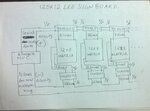
WP_20150822_005.jpg

Thanks for the reply all.
Hi burn and learn,
I am using ATmega16 microcontroller. I think it has SPI but I don't know what is it and how to use it.
The external frequency of the crystal is 20Mhz.
I also forgot to tell that I am using ULN2003 for rows to deal with the current issues. Please read the detailed description below.

Hi sunny sky guy,
I forgot to tell that I am using ULN2003 for rows to deal with the current issues. Please read the detailed description below.
Hi Fvm,
I have already mentioned that the latch pin (output enable pin 13) is connected to low permanently which means latch is activated all the time. Since the row is activated only after sending the 120 bit data to the shift registers there is no significance for latch. But as you said, Chinese displays, simultaneously send data and displays the previous data, can be done only through latch. But in my case I should find another way.

Hi KlausSt,
I think this is the solution if I did not connected latch output enable pin13 to low permanently. But in my case the latch is useless because it is low permanently.
I'm using an external crystal of frequency 20Mhz. The row is switched ON for 0.07ms and it is switched OFF for another 0.07ms (if this value is increased display will start to flicker largely. If value is decreased further the display will become dull). That means a total 0.14ms is for rows switching. If the time for sending one bit data to shift registers is 1ms then it would take a whole 120ms for sending the whole 120bit data. By adding row switching with this will get 120.14ms for one row completion. For 12 rows it is 1441.68ms. That means the display gets updated in 1441.68ms. This is too high, 70 times higher than recommended frame rate of 20ms. This is my problem.

I will explain here all the details :
About hardware:
MUC: Atmega16
External Quartz crystal: 20Mhz
Current per LED: 15ma
Rows are connected to negative polarity via ULN2003 to MUC.
Columns are connected to positive polarity via shift registers.
Each matrix is 8X12 led.
For each 20X12 led are connected to two now of ULN2003 (one ULN2003 have only 8 pins. I need 12to connect) ( ULN2003 has max 500ma capacity so I divided it to 20X12)
How it works:
1) 120bit data is send to shift registers
2) row is activated for 0.07ms.
3) row deactivated for 0.07ms.
4) 120bit data is send to shift registers for next row. And the process continues .

What i need:
I want to save idle time of the display when 120bit of data is being send. So that the display would not flicker.
 

I have already mentioned that the latch pin (output enable pin 13) is connected to low permanently which means latch is activated all the time. Since the row is activated only after sending the 120 bit data to the shift registers there is no significance for latch. But as you said, Chinese displays, simultaneously send data and displays the previous data, can be done only through latch. But in my case I should find another way.

Sounds still confused. HC595 has /OE pin 13 and RCLK pin 12. I'm talking about RCLK, not /OE. Pulling /OE low is O.K., the question is when to pulse RCLK.

Apart from less important details (signal polarity, using 1:16 or 1:8 mux rather than 1:12), your board can be operated exact the same way the industry standard LED cards are. Means, in your design each row should get a duty cycle of 1/12.

The scheme in #9 is basically O.K. and can be operated flicker-free with a microcontroller. Just a matter of right software.
 
Hi can you post the code, so that there will be no confusions and we can give you some solution.

Looks like every piece of segment doesnt gets enough ON time time to make the segment glow, may be you can increase the maximum possible anode voltage of the LED otherwise you can split the big stream in two or more parts.
 

Hi,

Two of your sentences:
If the time for sending one bit data to shift registers is 1ms then
I think it has SPI but I don't know what is it and how to use it.
It seems you are sending bit by bit with software. Don't do this.

SPI is the serial interface to transmit data to your HC595. It is fast and needs low software and low processing power.
With it you can easily transmit 1.000.000 bits per second to the HC595. (As long as your layout and signal lines are good enough)
So transmitting 120 bits may take only 120us.
--> read about SPI periferal of AVR.

Please try to meet my previously given timings.
Increase the ON time and decrease the OFF time.
With the SPI interface you could have about 1.4ms ON, and 0.2ms OFF (while transmitting 120 bits of row data).

Learn how to setup a timer interrupt to get an equal update rate of 1.6ms.
Learn how to use SPI.
Then your main loop has plenty of processing power to do other things (over 70%), for updating new display pattern or communication with PC or temperature sensing, or any other job you can think of. And your display is absolutely flicker free and bright - independent of the main loop tasks.

Take the couple of hours to learn and you will see the big benefit.

Klaus
 

I agree that you should use hardware SPI, if still possible with your design. But software "bit-banging" interface will work too. I don't understand how you arrived at 1 ms per bit, a few µs is well possible with pure software interface and 16 MHz AVR.
 

Thanks for the reply Fvm,

if you are talking about pin 13 it is ok. But how can pin 13 help my display flicker free. What is its purpose?

- - - Updated - - -

Thanks for the reply venkadesh,

I will send the code. The real problem with the code is the row will be activated only after sending 120 bits. And I don't know how to make both row activation and data sending simultaneously as FVM said.
 

Perhaps it helps if you sketch the signal waveforms. The usual scheme is to activate a row immediately after the new data for this row has been latched until the data for the next row is ready to be latched. It's an interleaved scheme, display the data of one row while the data for the next row are transmitted. The only requirement is that RCLK is wired as a separate signal through the HC595 chain.

In a HUB75 LED card interface, the respective signal is called LE.
 

Hi,

But how can pin 13 help my display flicker free. What is its purpose?

This is a misunderstanding - i think. Not pin 13 , but pin12 = RCLK.

Example:
* shift in 120 bits data for line1
* now give RCLK a positive edge, to send the data for line1 to the outputs.
* now enable the driver for line1 (line1 LED are active)
* now you may shift in 120 bits of data for line2 (still data for line1 are on the outputs of HC595 and the LEDs on line1 are still active)

--> switch from line1 to line2
* now disable driver for line1
* now give RCLK a positive edge, to send the data for line2 to the outputs.
* now enable driver for line2
--- (the three lines above need only some us of time. so the display is about 99% active)
* now you may shift in 120 bits of data for line3 (still data for line2 are on the outputs of HC595 and the LEDs on line2 are still active)

--> switch from line2 to line3
* now disable driver for line2
* now give RCLK a positive edge, to send the data for line3 to the outputs.
* now enable driver for line3
---
* now you may shift in 120 bits of data for line4 (still data for line3 are on the outputs of HC595 and the LEDs on line3 are still active)
... and so on.

the benefit is, that
* the display is 99% active, giving the most brightness
* there is no need to disable the display during transmit of 120 bits (same as above)
* there is no garbage on the LEDs during transmit
* you have plenty of time to slowly transmit the 120 bits (i recmmend to transmit faster than 120 bits per 1.6ms, for flickerfree display)
Slowly means, there is no need for 1Mbits/s, but at least 120bits/1.6ms = 75k bits/s = 13us/bit )

Klaus
 
Im posting the code, It's quite amateur since im not perfect in C program.


Code:
#define F_CPU 20000000UL
#include <avr/io.h>
#include <util/delay.h>

/***************************************

Configure Connections

****************************************/

#define HC595_PORT   PORTB
#define HC595_DDR    DDRB

#define HC595_DS_POS PB0      //Data pin (DS) pin location

#define HC595_SH_CP_POS PB1      //Shift Clock (SH_CP) pin location 
#define HC595_ST_CP_POS PB2      //Store Clock (ST_CP) pin location

/***************************************
Configure Connections ***ENDS***
****************************************/

//Initialize HC595 System

void HC595Init()
{
   //Make the Data(DS), Shift clock (SH_CP), Store Clock (ST_CP) lines output
   HC595_DDR|=((1<<HC595_SH_CP_POS)|(1<<HC595_ST_CP_POS)|(1<<HC595_DS_POS));
}


//Low level macros to change data (DS)lines
#define HC595DataHigh() (HC595_PORT|=(1<<HC595_DS_POS))

#define HC595DataLow() (HC595_PORT&=(~(1<<HC595_DS_POS)))

//Sends a clock pulse on SH_CP line
void HC595Pulse()
{
   //Pulse the Shift Clock

   HC595_PORT|=(1<<HC595_SH_CP_POS);//HIGH

   HC595_PORT&=(~(1<<HC595_SH_CP_POS));//LOW

}

//Sends a clock pulse on ST_CP line
void HC595Latch()
{
   //Pulse the Store Clock

   HC595_PORT|=(1<<HC595_ST_CP_POS);//HIGH
  

   HC595_PORT&=(~(1<<HC595_ST_CP_POS));//LOW
   
}


/*

Main High level function to write a single byte to
Output shift register 74HC595. 

Arguments:
   single byte to write to the 74HC595 IC

Returns:
   NONE

Description:
   The byte is serially transfered to 74HC595
   and then latched. The byte is then available on
   output line Q0 to Q7 of the HC595 IC.

*/
void HC595Write(uint8_t data,int l)
{
   //Send each 8 bits serially

   //Order is MSB first
   for(uint8_t i=0;i<l;i++)
   {

      //Output the data on DS line according to the
      //Value of MSB
      if(data & 0b10000000)
      {
         //MSB is 1 so output high

         HC595DataHigh();
      }
      else
      {
         //MSB is 0 so output high
         HC595DataLow();
      }

      HC595Pulse();  //Pulse the Clock line
      data=data<<1;  //Now bring next bit at MSB position

   }

   //Now all 8 bits have been transferred to shift register
   //Move them to output latch at one
   HC595Latch();

   
}

/*

Simple Delay function approx 0.5 seconds

*/


void delayfn(uint8_t loop)
{

		
		 if(loop<7){
		
		 PORTA=(1<<loop);
		 
		 _delay_ms(0.2); 

		 PORTA=(0<<loop);               //Wait 

		 }else{

		 
		  PORTD=(1<<loop-7);
		 
		 _delay_ms(0.2); 

		 PORTD=(0<<loop-7); 

		 }


}

int main()
{
   uint8_t led_pattern_1[480]={


0b11000111,
0b11101111,
0b11101111,
0b11111111,
0b11111111,
0b11111111,
0b01111110,
0b01111110,
0b00111100,
0b00111100,
0b00011000,
0b00000000,

0b00000000,
0b00000000,
0b00000000,
0b00000000,
0b00000000,
0b00000000,
0b00000000,
0b00000000,
0b00000000,
0b00000000,
0b00000000,
0b00000000,


/////

0b11000111,
0b11101111,
0b11101111,
0b11111111,
0b11111111,
0b11111111,
0b01111110,
0b01111110,
0b00111100,
0b00111100,
0b00011000,
0b00000000,


0b00000000,
0b00000000,
0b00000000,
0b00000000,
0b00000000,
0b00000000,
0b00000000,
0b00000000,
0b00000000,
0b00000000,
0b00000000,
0b00000000,


0b11000111,
0b11101111,
0b11101111,
0b11111111,
0b11111111,
0b11111111,
0b01111110,
0b01111110,
0b00111100,
0b00111100,
0b00011000,
0b00000000,


0b00000000,
0b00000000,
0b00000000,
0b00000000,
0b00000000,
0b00000000,
0b00000000,
0b00000000,
0b00000000,
0b00000000,
0b00000000,
0b00000000,

0b01111111,
0b01111111,
0b00011100,
0b00011100,
0b00011100,
0b00011100,
0b00011100,
0b00011100,
0b00011100,
0b00011100,
0b01111111,
0b01111111,


0b00000000,
0b00000000,
0b00000000,
0b00000000,
0b00000000,
0b00000000,
0b00000000,
0b00000000,
0b00000000,
0b00000000,
0b00000000,
0b00000000,

0b01100000,
0b01100000,
0b01100000,
0b01100000,
0b01100000,
0b01100000,
0b01100000,
0b01100000,
0b01100000,
0b01100000,
0b01111111,
0b01111111,


0b00011100,
0b00111110,
0b01111111,
0b01100011,
0b01100011,
0b01100011,
0b01100011,
0b01100011,
0b01100011,
0b01111111,
0b00111110,
0b00011100,

0b01100011,
0b01100011,
0b01100011,
0b01100011,
0b01100011,
0b01100011,
0b01100011,
0b01100011,
0b01100011,
0b00110110,
0b00011100,
0b00001000,


0b01111111,
0b01111111,
0b01100000,
0b01100000,
0b01100000,
0b01111110,
0b01111110,
0b01100000,
0b01100000,
0b01100000,
0b01111111,
0b01111111,


0b00000000,
0b00000000,
0b00000000,
0b00000000,
0b00000000,
0b00000000,
0b00000000,
0b00000000,
0b00000000,
0b00000000,
0b00000000,
0b00000000,


0b01100011,
0b01100011,
0b01100011,
0b01100011,
0b01100011,
0b01100011,
0b00111110,
0b00011100,
0b00011100,
0b00011100,
0b00011100,
0b00011100,


0b00011100,
0b00111110,
0b01111111,
0b01100011,
0b01100011,
0b01100011,
0b01100011,
0b01100011,
0b01100011,
0b01111111,
0b00111110,
0b00011100,


/////

0b01100011,
0b01100011,
0b01100011,
0b01100011,
0b01100011,
0b01100011,
0b01100011,
0b01100011,
0b01100011,
0b01100011,
0b00111110,
0b00011100,

0b00000000,
0b00000000,
0b00000000,
0b00000000,
0b00000000,
0b00000000,
0b00000000,
0b00000000,
0b00000000,
0b00000000,
0b00000000,
0b00000000,


0b01100011,
0b01110111,
0b01110111,
0b01110111,
0b01111111,
0b01111111,
0b01111111,
0b01101011,
0b01101011,
0b01101011,
0b01100011,
0b01100011,


0b01100011,
0b01100011,
0b01100011,
0b01100011,
0b01100011,
0b01100011,
0b00111110,
0b00011100,
0b00011100,
0b00011100,
0b00011100,
0b00011100,


0b00000000,
0b00000000,
0b00000000,
0b00000000,
0b00000000,
0b00000000,
0b00000000,
0b00000000,
0b00000000,
0b00000000,
0b00000000,
0b00000000,


0b01100000,
0b01100000,
0b01100000,
0b01100000,
0b01100000,
0b01100000,
0b01100000,
0b01100000,
0b01100000,
0b01100000,
0b01111111,
0b01111111,


0b00111110,
0b01111111,
0b01100011,
0b01100011,
0b01100011,
0b01111111,
0b01111111,
0b01100011,
0b01100011,
0b01100011,
0b01100011,
0b01100011,


0b01100001,
0b01100011,
0b01100110,
0b01101100,
0b01111000,
0b01110000,
0b01110000,
0b01111000,
0b01101100,
0b01100110,
0b01100011,
0b01100001,


0b00111110,
0b01111111,
0b01100011,
0b01100000,
0b01100000,
0b01111110,
0b00111111,
0b00000011,
0b00000011,
0b01100011,
0b01111111,
0b00111110,


0b01100011,
0b01100011,
0b01100011,
0b01100011,
0b01100011,
0b01111111,
0b01111111,
0b01100011,
0b01100011,
0b01100011,
0b01100011,
0b01100011,

0b01100011,
0b01110111,
0b01110111,
0b01110111,
0b01111111,
0b01111111,
0b01111111,
0b01101011,
0b01101011,
0b01101011,
0b01100011,
0b01100011,


0b01111111,
0b01111111,
0b00011100,
0b00011100,
0b00011100,
0b00011100,
0b00011100,
0b00011100,
0b00011100,
0b00011100,
0b01111111,
0b01111111,

0b01100001,
0b01100011,
0b01100110,
0b01101100,
0b01111000,
0b01110000,
0b01110000,
0b01111000,
0b01101100,
0b01100110,
0b01100011,
0b01100001,


0b01100011,
0b01100011,
0b01100011,
0b01100011,
0b01100011,
0b01100011,
0b01100011,
0b01100011,
0b01100011,
0b01100011,
0b00111110,
0b00011100,

0b01111111,
0b01111111,
0b00011100,
0b00011100,
0b00011100,
0b00011100,
0b00011100,
0b00011100,
0b00011100,
0b00011100,
0b00011100,
0b00011100,

0b01111111,
0b01111111,
0b00011100,
0b00011100,
0b00011100,
0b00011100,
0b00011100,
0b00011100,
0b00011100,
0b00011100,
0b00011100,
0b00011100,

0b01100011,
0b01100011,
0b01100011,
0b01100011,
0b01100011,
0b01100011,
0b00111110,
0b00011100,
0b00011100,
0b00011100,
0b00011100,
0b00011100,


0b00000000,
0b00000000,
0b00000000,
0b00000000,
0b00000000,
0b00000000,
0b00000000,
0b00000000,
0b00000000,
0b00000000,
0b00000000,
0b00000000,


0b11000111,
0b11101111,
0b11101111,
0b11111111,
0b11111111,
0b11111111,
0b01111110,
0b01111110,
0b00111100,
0b00111100,
0b00011000,
0b00000000,

0b00000000,
0b00000000,
0b00000000,
0b00000000,
0b00000000,
0b00000000,
0b00000000,
0b00000000,
0b00000000,
0b00000000,
0b00000000,
0b00000000,

0b11000111,
0b11101111,
0b11101111,
0b11111111,
0b11111111,
0b11111111,
0b01111110,
0b01111110,
0b00111100,
0b00111100,
0b00011000,
0b00000000,

0b00000000,
0b00000000,
0b00000000,
0b00000000,
0b00000000,
0b00000000,
0b00000000,
0b00000000,
0b00000000,
0b00000000,
0b00000000,
0b00000000,


/////

0b00000000,
0b00000000,
0b00000000,
0b00000000,
0b00000000,
0b00000000,
0b00000000,
0b00000000,
0b00000000,
0b00000000,
0b00000000,
0b00000000,

0b11000111,
0b11101111,
0b11101111,
0b11111111,
0b11111111,
0b11111111,
0b01111110,
0b01111110,
0b00111100,
0b00111100,
0b00011000,
0b00000000,


0b00000000,
0b00000000,
0b00000000,
0b00000000,
0b00000000,
0b00000000,
0b00000000,
0b00000000,
0b00000000,
0b00000000,
0b00000000,
0b00000000,


/////

  };

  ////////one time registration

  uint8_t led_pattern_2[480]={

0b00000000,
0b00000000,
0b00000000,
0b00000000,
0b00000000,
0b00000000,
0b00000000,
0b00000000,
0b00000000,
0b00000000,
0b00000000,
0b00000000,

0b11000111,
0b11101111,
0b11101111,
0b11111111,
0b11111111,
0b11111111,
0b01111110,
0b01111110,
0b00111100,
0b00111100,
0b00011000,
0b00000000,


0b00000000,
0b00000000,
0b00000000,
0b00000000,
0b00000000,
0b00000000,
0b00000000,
0b00000000,
0b00000000,
0b00000000,
0b00000000,
0b00000000,

0b11000111,
0b11101111,
0b11101111,
0b11111111,
0b11111111,
0b11111111,
0b01111110,
0b01111110,
0b00111100,
0b00111100,
0b00011000,
0b00000000,


0b00000000,
0b00000000,
0b00000000,
0b00000000,
0b00000000,
0b00000000,
0b00000000,
0b00000000,
0b00000000,
0b00000000,
0b00000000,
0b00000000,

0b11000111,
0b11101111,
0b11101111,
0b11111111,
0b11111111,
0b11111111,
0b01111110,
0b01111110,
0b00111100,
0b00111100,
0b00011000,
0b00000000,


0b00000000,
0b00000000,
0b00000000,
0b00000000,
0b00000000,
0b00000000,
0b00000000,
0b00000000,
0b00000000,
0b00000000,
0b00000000,
0b00000000,

0b01100011,
0b01100011,
0b01100011,
0b01100011,
0b01100011,
0b01100011,
0b00111110,
0b00011100,
0b00011100,
0b00011100,
0b00011100,
0b00011100,


0b00011100,
0b00111110,
0b01111111,
0b01100011,
0b01100011,
0b01100011,
0b01100011,
0b01100011,
0b01100011,
0b01111111,
0b00111110,
0b00011100,

0b01100011,
0b01100011,
0b01100011,
0b01100011,
0b01100011,
0b01100011,
0b01100011,
0b01100011,
0b01100011,
0b01100011,
0b00111110,
0b00011100,


///K

0b00000000,
0b00000000,
0b00000000,
0b00000000,
0b00000000,
0b00000000,
0b00000000,
0b00000000,
0b00000000,
0b00000000,
0b00000000,
0b00000000,

////E


0b00111110,
0b01111111,
0b01100011,
0b01100011,
0b01100011,
0b01111111,
0b01111111,
0b01100011,
0b01100011,
0b01100011,
0b01100011,
0b01100011,

///R

0b01111100,
0b01111110,
0b01100011,
0b01100011,
0b01100011,
0b01111110,
0b01111100,
0b01111000,
0b01101100,
0b01100110,
0b01100011,
0b01100011,


//////A

0b01111111,
0b01111111,
0b01100000,
0b01100000,
0b01100000,
0b01111110,
0b01111110,
0b01100000,
0b01100000,
0b01100000,
0b01111111,
0b01111111,


///L

0b00000000,
0b00000000,
0b00000000,
0b00000000,
0b00000000,
0b00000000,
0b00000000,
0b00000000,
0b00000000,
0b00000000,
0b00000000,
0b00000000,
//////A

0b01100011,
0b01110111,
0b01110111,
0b01110111,
0b01111111,
0b01111111,
0b01111111,
0b01101011,
0b01101011,
0b01101011,
0b01100011,
0b01100011,


0b01100011,
0b01100011,
0b01100011,
0b01100011,
0b01100011,
0b01100011,
0b00111110,
0b00011100,
0b00011100,
0b00011100,
0b00011100,
0b00011100,


///P

0b00000000,
0b00000000,
0b00000000,
0b00000000,
0b00000000,
0b00000000,
0b00000000,
0b00000000,
0b00000000,
0b00000000,
0b00000000,
0b00000000,

///S


0b00111110,
0b01111111,
0b01100011,
0b01100000,
0b01100000,
0b01111110,
0b00111111,
0b00000011,
0b00000011,
0b01100011,
0b01111111,
0b00111110,

////C


0b00011100,
0b00111110,
0b01111111,
0b01100011,
0b01100011,
0b01100011,
0b01100011,
0b01100011,
0b01100011,
0b01111111,
0b00111110,
0b00011100,


0b01100011,
0b01100011,
0b01100011,
0b01100011,
0b01100011,
0b01100011,
0b01100011,
0b01100011,
0b01100011,
0b01100011,
0b00111110,
0b00011100,

///R

0b01100000,
0b01100000,
0b01100000,
0b01100000,
0b01100000,
0b01100000,
0b01100000,
0b01100000,
0b01100000,
0b01100000,
0b01111111,
0b01111111,

////E


0b00000000,
0b00000000,
0b00000000,
0b00000000,
0b00000000,
0b00000000,
0b00000000,
0b00000000,
0b00000000,
0b00000000,
0b00000000,
0b00000000,

/////G

0b11000111,
0b11101111,
0b11101111,
0b11111111,
0b11111111,
0b11111111,
0b01111110,
0b01111110,
0b00111100,
0b00111100,
0b00011000,
0b00000000,


0b00000000,
0b00000000,
0b00000000,
0b00000000,
0b00000000,
0b00000000,
0b00000000,
0b00000000,
0b00000000,
0b00000000,
0b00000000,
0b00000000,

///S


0b11000111,
0b11101111,
0b11101111,
0b11111111,
0b11111111,
0b11111111,
0b01111110,
0b01111110,
0b00111100,
0b00111100,
0b00011000,
0b00000000,


0b00000000,
0b00000000,
0b00000000,
0b00000000,
0b00000000,
0b00000000,
0b00000000,
0b00000000,
0b00000000,
0b00000000,
0b00000000,
0b00000000,

///R
0b11000111,
0b11101111,
0b11101111,
0b11111111,
0b11111111,
0b11111111,
0b01111110,
0b01111110,
0b00111100,
0b00111100,
0b00011000,
0b00000000,


0b00000000,
0b00000000,
0b00000000,
0b00000000,
0b00000000,
0b00000000,
0b00000000,
0b00000000,
0b00000000,
0b00000000,
0b00000000,
0b00000000,

///T


0b00000000,
0b00000000,
0b00000000,
0b00000000,
0b00000000,
0b00000000,
0b00000000,
0b00000000,
0b00000000,
0b00000000,
0b00000000,
0b00000000,

///I


};


//////passport registration

  uint8_t led_pattern_3[480]={


0b00000000,
0b00000000,
0b00000000,
0b00000000,
0b00000000,
0b00000000,
0b00000000,
0b00000000,
0b00000000,
0b00000000,
0b00000000,
0b00000000,


};


//////end of array


   //Initialize HC595 system

   HC595Init();
   DDRA=0xFF;
   PORTA=0;
   DDRD=0xFF;
   PORTD=0;
   int speed;
   speed=11; //speed of scroll increase to decrease speed
   int array;
   array=15;  //no of matrix *****dontforget****
   int l,j,m,n,p,s,count;
   l=0;
   m=0;
   n=0;
   s=0;
   int height=12;// no of rows for us it is 12
   int matrix=480;//no of array
   matrix=matrix-(array*12);

   int cartoonsteps=4;//cartoon frames

  void refresh(){

  for(uint8_t k=0;k<20;k++)///speed of the scroll
      {

   int loop=0; //for the scanning rows 1-12 1-12...

      for(uint8_t i=0;i<12;i++)
      {

		for(uint8_t q=0;q<12;q++){
      
	     HC595Write(led_pattern_1[q],8);//this is for full 8 row data sending

	   }
	 
       delayfn(loop);

       loop=loop+1;

	  }

	  }
}


   while(1)
   {

for(uint8_t k=0;k<speed;k++)///speed of the scroll
      {
////*******cartoon starts here*****/////

      int loop=0; //for the scanning rows 1-12 1-12...


      for(uint8_t i=0;i<12;i++)
      {
        
        p=n;

		for(uint8_t q=0;q<array;q++){

		if(count==1){
		
		HC595Write(led_pattern_2[i+p],8);//this is for full 8 row data sending
		
		}else{
		
		HC595Write(led_pattern_1[i+p],8);//this is for full 8 row data sending
		
		}


         p=p+12;       

	   }
	 
       delayfn(loop);

       loop=loop+1;

	  }


	  }

	  n=n+12;

	  if(n>matrix){n=0;int n1=0;refresh();if(count==1){count=0;}else{count=1;}}
//text 1 finish


	  //loop for entire cycle

////*******cartoon ends here*****/////


}


}
 

For 5mm Red/Amber is usually 10:1 for pk/max since they are 2V
For 5mm Green/Blue/White is 5:1 since they are >3.2V

ie. 100:20 mA= 5:1 mux ratio

This does not improve even with modern LED's as the efficacy will drop substantially. Modern LEDs can handle higher Avg currents in SMD but the peak/rated DC is still the same.

Although you can get very high brightness LEDs to operate as indicator displays at say 20% of max for the average and thus extend your MUX ratio using narrow angle LEDs.

Unfortunately Muxing 12 is a challenge that requires more thought and experience on what you are try to do. ie. specs or requirements.

Flickering brightness is most likely due to higher switch resistance in the ROw drivers which causes that row to dim when more LEDs are on.

THus if you have 120 LEDS with say 240 Ohms series limiting current per column , net net Rs is 2 Ohms and your ROw driver must be < 5% of this to have a minimal fluctuation .. ie a switch Rce or RdsOn of 2/20= <= 100 mOhm.

We need H/W Details Please !! SChematic/ part numbers on LEDs
 

Status
Not open for further replies.

Similar threads

Part and Inventory Search

Welcome to EDABoard.com

Sponsor

Back
Top