Continue to Site

Welcome to EDAboard.com

Welcome to our site! EDAboard.com is an international Electronics Discussion Forum focused on EDA software, circuits, schematics, books, theory, papers, asic, pld, 8051, DSP, Network, RF, Analog Design, PCB, Service Manuals... and a whole lot more! To participate you need to register. Registration is free. Click here to register now.

DC blocking capacitor

Status
Not open for further replies.

Antenna (^.^)

Member level 3
Member level 3
Joined
Jul 6, 2015
Messages
54
Helped
0
Reputation
0
Reaction score
0
Trophy points
6
Activity points
499
Hi everybody,

I need to use some SPST RF switches for five different frequencies. However it says I need to use DC blocking capacitors for the RF switch to work.
My desired frequencies are 2.4, 2.1, 1.8, 1.6, 0.9 GHz.

Could anyone please give me a starting point on how to determine the values for the DC block capacitors?

I have read about Xc and SRF etc but I am not really getting it....:cry:
 

You generally want the capacitor reactance (impedance) to be much less than the circuit impedance.
The reactance of a capacitor is Xc = 1/(2*pi*f*C) where f is the frequency of operation.
Thus the higher the frequency and the larger the capacitor, the smaller the reactance.
Thus for a typical 50Ω circuit impedance, you probably should have the capacitive impedance no more that about 1% of 50Ω or 0.5Ω.
So, for example, at 2.4GHz frequency, the capacitor should be no smaller than C = 1/(2*pi*2.4GHz*0.5Ω) = 132pF.
 
umm ok so we use Xc = 1/(2*pi*f*C) , and we want an Xc reactance which is a lot smaller than circuit impedance. Thus for a small Xc reactance, and with a high frequency (GHz), the capacitor value I need should be high.
Knowing this I then rearrange Xc = 1/(2*pi*f*C) to solve for a suitable C value, but I don't quite understand yet how circuit impedance comes in... Furthermore, how to obtain circuit impedance -by calculation or arbitrary choice like 50Ω?
 

50 Ohm is the standard for RF for many reasons and 75 for video, and others for differential signals.

When it comes to measuring s parameters , 50 Ohms is the standard.

But internal SAW filters for example can be any impedance that is suitable but external interfaces follow the most common standards.

I suggest you not use expensive RF switches or cheap unsuitable mechanical switches.

THis is what I recommend. https://scholar.lib.vt.edu/theses/available/etd-05072012-141855/unrestricted/Wan_HM_T_2012.pdf
A 1P5T active switch.

SRF dissipation factor and loss tangent are important criteria for choosing a DC blocking cap.
I would chose one that meets your criteria for insertion loss and return loss, which could be around 47 pF at 1GHz from my experience.

You must define the acceptance criteria for all s parameters for power level, isolation and loss before ANY selection is considered.
 

Hi everybody,

I need to use some SPST RF switches for five different frequencies. However it says I need to use DC blocking capacitors for the RF switch to work.
My desired frequencies are 2.4, 2.1, 1.8, 1.6, 0.9 GHz.

Could anyone please give me a starting point on how to determine the values for the DC block capacitors?

I have read about Xc and SRF etc but I am not really getting it....:cry:


In fact, as long as a series capacitor is just DC blocking.

Thus,

1. You can regard it as matching component, and determine its value by general matching tuning steps.

2. Just regard it as DC blocking, and you hope it doesn't impact your impedance.
If so, put 100 pF, because you will find that a 100 pF series capacitor hardly impacts impedance.
 

Just regard it as DC blocking, and you hope it doesn't impact your impedance.
If so, put 100 pF, because you will find that a 100 pF series capacitor hardly impacts impedance.

Why will 100pF not affect impedance? Could you please explain a bit more?
 

Why will 100pF not affect impedance? Could you please explain a bit more?

According to CAPACITIVE REACTANCE formula :

Xc = 1/jwc

That is to say, more the capacitor value, lower the Xc.
If capacitor value were infinite, Xc would be zero.
Of course, in reality, there is no capacitor with infinite value.
But , at least, we realize that more the capacitor value, closer to 0 Ohm resistor and less effect on impedance.

Nevertheless,
it is not necessary for capacitor value to uF level.
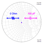
According to simulation,
you can find that mere 100 pF does not impact impedance at all.

image001.png
 

My desired frequencies are 2.4, 2.1, 1.8, 1.6, 0.9 GHz.


I have read about Xc and SRF etc but I am not really getting it....


100pF is 2Ω @ 0.9GHz with drops to 0.5Ω @ 2.4GHz

Inductance of cap causes Series Resonant Frequency (SRF).

Choose small SMT RF ceramic caps with SRF rating above 2.4GHz with margin to include traces inductance.

If the Return Loss (s22) of a passive matched source is unacceptable with series cap, choose a slightly higher value or use conjugate matched load.
 

Status
Not open for further replies.

Similar threads

Part and Inventory Search

Welcome to EDABoard.com

Sponsor

Back
Top