Warpspeed
Advanced Member level 5

- Joined
- May 23, 2015
- Messages
- 2,366
- Helped
- 773
- Reputation
- 1,548
- Reaction score
- 789
- Trophy points
- 1,393
- Location
- Melbourne, Australia
- Activity points
- 20,317
Sinewave inverters seem to be a subject of particular interest here on the Forum, and high frequency PWM seems to be the method of choice.
But it is not the only method.
Generating PWM sinewave is not that difficult, but filtering out the high frequency switching noise to an acceptable level without creating other problems can often be a challenge.....
Its the post switching filtering that is the problem.
Any shunt impedance is going to load down the inverter and create a constant useless power drain. Series impedance just degrades voltage regulation, and loses us even more precious power.
Hard switched modified sinewave inverters can be quite useful, but many motor loads are not happy with this and run hot, or complain acoustically.
So the low harmonic distortion of something much closer to a pure sinewave becomes well worth the effort for mixed loads typical of a domestic application.
Where I am, harmonic distortion of incoming grid power usually measures around 4%, sometimes a bit more, sometimes less. A typical modified sinewave inverter has something like 40% actual measured distortion. It can vary depending on the exact duty cycle and slew rate, but its always pretty high.
So something around 4% harmonic distortion should do us very nicely, anything better than that is probably overkill for normal domestic power.
So the idea behind all this is to come up with a simple straightforward easily designed and efficient power output stage that requires little or no post filtering to reach (or better) our harmonic distortion goal.
It can be done by generating a multi step sinewave.
The more and smaller the steps, the closer it approaches a sinewave.
Although the voltage goes up and down in discrete jumps, the current waveform in an inductive load will look far smoother. So its much more motor friendly than the voltage waveform might appear.
The idea is to start off with something that looks exactly like a modified sinewave inverter, because that is what it is.
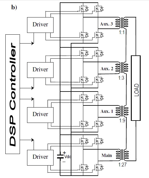
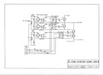
Basically (for this example) something that hard switches from 0V / +300v / 0v / -300v / 0v
A second "medium" power inverter also hard switches across the same +300v and -300v dc rails and drives a transformer with an exact 3:1 step down ratio.
The secondary voltage can then be either zero, +100v or -100v
The secondary of this transformer is connected in series with the "big" inverter so by adding or subtracting 100 volts we can generate 100 volt steps from -300v to +300v.
In fact three steps up, zero, and three steps down.
Harmonic distortion should be around a measured 11% without filtering, and its all hard switched at low frequency for lowest switching and conduction losses.
We then add a third "small" inverter with a 9:1 transformer to generate 33 volt steps.
That gives us nine steps up to +300v plus an extra step to +333v, ten steps up and ten down each half cycle.
Or 21 steps peak to peak including zero.
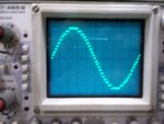
Measured distortion is around 4% and it looks pretty nice on an oscilloscope. You could fit a fourth stage and very easily get well below 2% distortion but I never bothered.
The drive waveforms are very easy to generate.
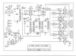
A long counter is clocked at 3.2768 Mhz and directly addresses a 2Kx8 EPROM.
The EPROM just cycles through every address sequentially, 10uS per address, completing 50 cycles per second. An eight bit latch on the data outputs locks in stable data to drive the IGBTs in the three half bridge power output stages.
Additional IGBTs clamp the respective output to ground when the required output is zero volts for each of the three output stages.
It all works very well, its simple, very efficient, and worked very first attempt without any problems.
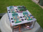
The two transformers I just happened to already have here worked perfectly for a 1.5Kw prototype.
One is 240v to 80v (40+40v) toroid giving a 3:1 ratio.
The other 240v to 26v, close enough to 9:1 ratio.
The voltage steps are not perfect, but are close enough to easily meet the target harmonic distortion.
Its been a wonderfully simple project where everything worked very first go without a single problem !!!
Next step will be to fit larger more optimum transformers to get me up to the 4-5Kw range.
Current limit forces the main counter to zero, which is the exact zero crossing point in the data.
Reset the main counter, and everything turns off in only 1.5uS.
A 20A 1mH powdered iron dimmer choke (standard fitment for large SCR light dimmers) in the ac output limits di/dt so even with a sudden dead short, the IGBTs are all turned off before fault current can rise to dangerous levels.
This choke also knocks the edges off the output waveform, but EMI problems are going to be pretty minimal anyway using this approach.
This thing works far better than I ever dared to hope.
I have been messing about with PWM inverters for years, this wins hands down for lack of problems.
Its still at the "Mickey Mouse" prototype stage but working well enough to fully test.
Cheers, Tony.


