Continue to Site

Welcome to EDAboard.com

Welcome to our site! EDAboard.com is an international Electronics Discussion Forum focused on EDA software, circuits, schematics, books, theory, papers, asic, pld, 8051, DSP, Network, RF, Analog Design, PCB, Service Manuals... and a whole lot more! To participate you need to register. Registration is free. Click here to register now.

Ir2110 H bridge not working at High voltage DC 220V with PWM 16Khz

Status
Not open for further replies.

suri007

Newbie level 5
Newbie level 5
Joined
May 3, 2013
Messages
8
Helped
0
Reputation
0
Reaction score
0
Trophy points
1,281
Activity points
1,360
Hi,

we are implementing a DC motor speed controller using Full H bridge and IR2110 drivers.

The circuit works good for 12V , but if we wish to control a 220V DC load the circuit is not working.

The high side drivers (S1 and S3) of 2 IR2110's are always ON, eventhough we give inputs to S1 and S4 (forward direction). I am using PWM frequency of 16Khz , will this have any impact on the circuit working conditions. If so suggest me the PWM frequency along with the switching sequence i need to use

Regards,
Suresh
 

YOu better review your Gate Voltage levels for turn off and timing vs Threshold. Note detailed selection of RC+diode control of gate voltage.

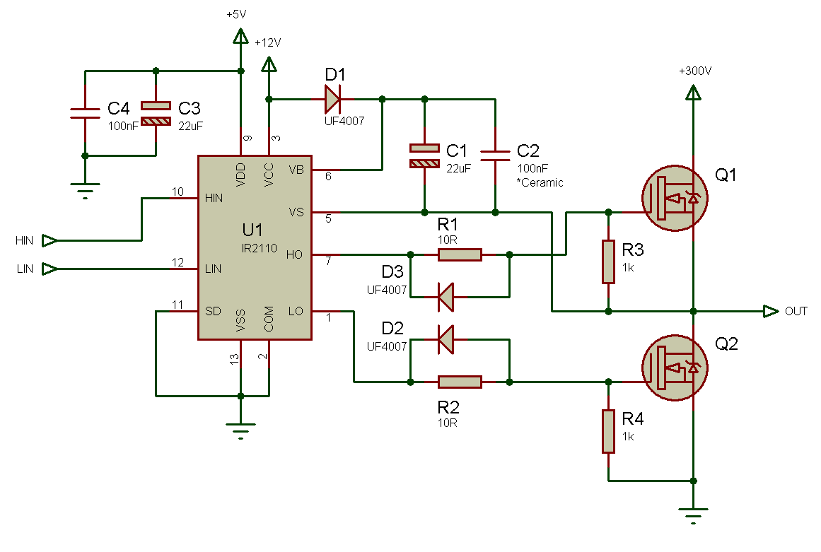
This following design uses fast turn Off and slow turn on. Dead time is critical, which is controlled in this way.

IR2110+-+2.png
 

Hi SunnySkyguy,

Please find the attached motor driver in H bridge configuration what i am using along with the component values. Please check and suggest me what i have to change

Regards,
Suresh
 

Attachments

  • MOTOR DRIVER.jpg
    MOTOR DRIVER.jpg
    104.8 KB · Views: 270

I have problems with the original report:
The high side drivers (S1 and S3) of 2 IR2110's are always ON, eventhough we give inputs to S1 and S4 (forward direction).
Besides apparently confused switch numbers, what do you exactly observe? High side drivers always on with 220V bus voltage means that the output transistors will be immediately destroyed. Did you have burned H-bridge or under which conditions did you see "high-side drivers always on"?

No obvious problem with the shown driver circuit, except for a missing Vdd bypass capacitor.
 

Hi FvM,

I will give u a summary of the circuits operation

S1, S3 are high side drivers and PWM signal is applied to these as inputs
S2, S4 are low side drivers

When S1 and S4 conduct motor will run in forward direction
When S3 and S2 conduct motor will run in reverse direction

I am trying to run a motor lets say in forward direction , so the condition at the inputs would be
S1i = PWM signal
S2i = 0V
S3i = 0V
S4i = 5V

Ideally motor should run, For a 12V DC supply and motor load when i give this combination motor runs successfully and i see gates of S1o and S4o are conducting. But when i try with 220V DC supply and motor load with the same input combinations i see S1o and S3o are conducting instead of S1o and S4o. No matter what combination i follow, the high side drivers S1o and S3o are always ON and S2o, S4o are always off. I do not understand why this is happening

PS: S1i is input to high side of Ir2110 and S10 is high side output of Ir2110 and so on

I donot see any Drivers blowing away and the circuit is simple fine.


Regards,
Suresh

- - - Updated - - -

Hi Fvm,

What do you mean by "No obvious problem with the shown driver circuit, except for a missing Vdd bypass capacitor.

Please explain and what is the value i need to have for the vdd bypass capacitor

Regards,
Suresh

- - - Updated - - -


Regards,
Suresh
 

You would be well advised to measure SUpply glitch current and Gate Voltage dead time vs Temp. and consider 22R+diode with high Gate capacitance during switching. It helps to prevent Shoot-thru failures from thermal runaway.

Vdd is <<1mA so any decoupling cap should work.

**broken link removed**
 

The observed behaviour can't be explained with regular gate driver behaviour. Something must be wrong with your ciruit.
 

Hi SunnySkyGuy/FVM,

Do you think this would be some problem with circuit itself, or with software? Do i need to use low voltage boot strap capacitor other tha 65V what i am using now, will this help.

And can u tell me what Switching diodes are faster than UF 4007

Regards
Suresh
 

I am having the same problem as Suri007. The high side remaining on all the time. Need help if the solution was found already.
 

You need to post more of your circuit if we are to fault find it - could be errors in your driving signals, or incorrect build...
 
S1, S3 are high side drivers and PWM signal is applied to these as inputs
S2, S4 are low side drivers
I am trying to run a motor lets say in forward direction , so the condition at the inputs would be
S1i = PWM signal
S2i = 0V
S3i = 0V
S4i = 5V

Hi ... why you don't just apply the PWM signal to the low side transistors and leave the 5v continuous ON to the high side to avoid problems with the BS capacitor ... and 5v Vdd is working with 12v motor just fine so you should use 15V Vdd when working up to 500v .
 

You need to post more of your circuit if we are to fault find it - could be errors in your driving signals, or incorrect build...

you all should review your builds again even if someone else has the same problem ... I saw your circuit and the right hand side has some inverted letters " Is that an indication for something in the real world ?"
 

First, what are your MOSFET's P/N ? ... I guess you're using p-channel MOSFET's for the high side
 

Status
Not open for further replies.

Part and Inventory Search

Welcome to EDABoard.com

Sponsor

Back
Top