Continue to Site

Welcome to EDAboard.com

Welcome to our site! EDAboard.com is an international Electronics Discussion Forum focused on EDA software, circuits, schematics, books, theory, papers, asic, pld, 8051, DSP, Network, RF, Analog Design, PCB, Service Manuals... and a whole lot more! To participate you need to register. Registration is free. Click here to register now.

Speedometer Circuit Board

Status
Not open for further replies.

ultra 15f

Newbie level 6
Joined
Feb 25, 2014
Messages
14
Helped
0
Reputation
0
Reaction score
0
Trophy points
1
Activity points
103
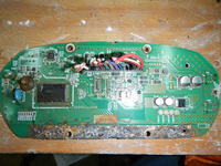
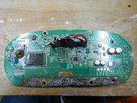
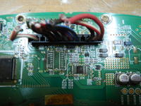
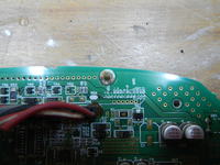
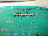
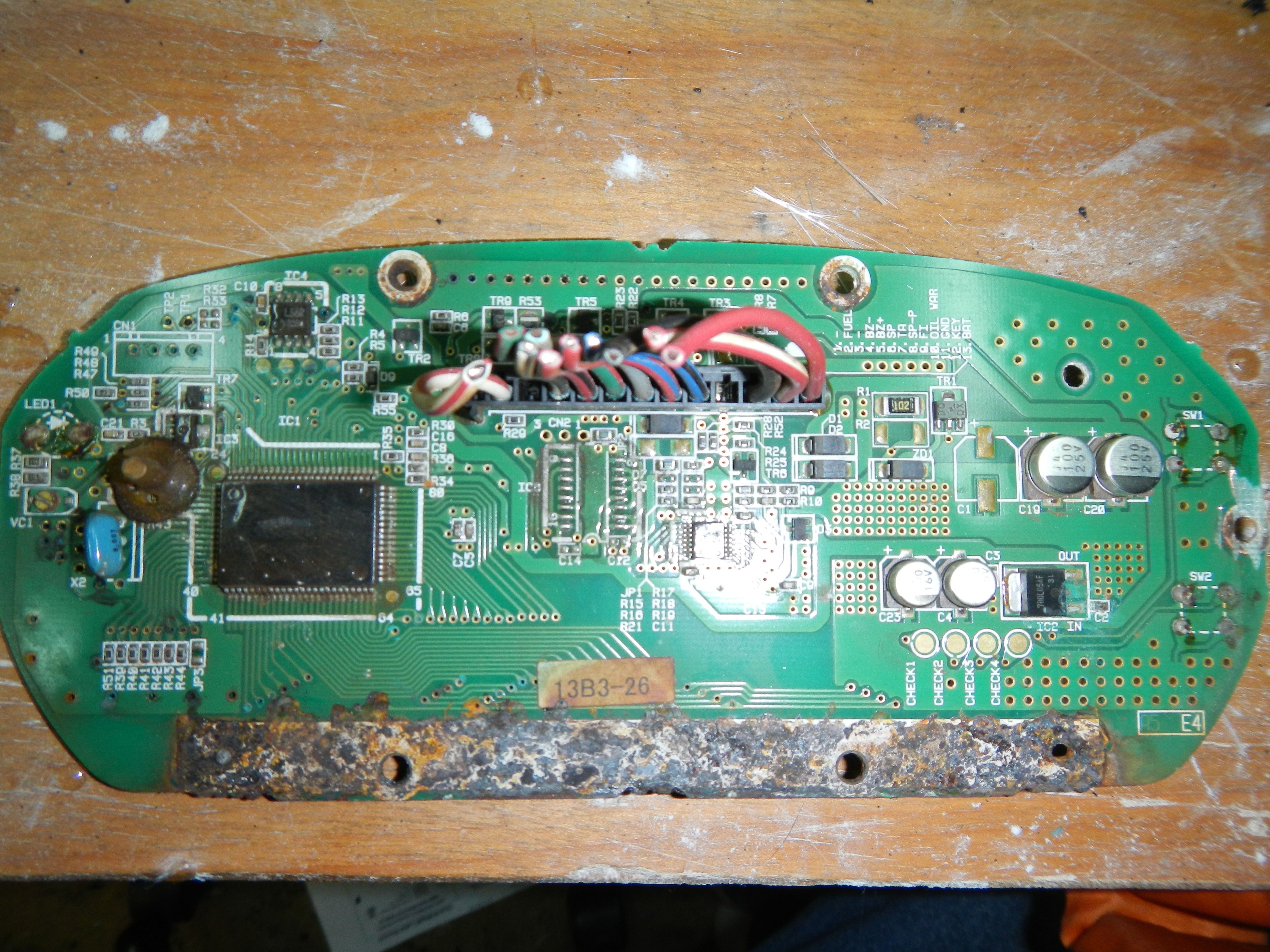
Not sure if im putting this in the right thread but i have a digital speedometer that the factory limits it to only read up 70 mph even thought it has the digits to go up to 199 mph. The speedo works on a 12v square wave and its input #6 red and green wire. Could someone please help me diagnose what is making it stop at 70 mph and help me find a way to make it read higher. Here are some pics of the board let me know what areas you might need a closer picture. Thanks for your help.


That chip is probably a microcontroller and if the limit is implemented in software there is nothing you can do (unless you manage to write the code from scratch and reprogram it)
 

Was it always limited to 70 mph? That seems a bit low. What model car is it out of? Have you searched for a group devoted to that model?

In a worse case scenario, you might make a manual "speed switch" that would make the indicated speed half of the true speed. To help you do that, we would need to know a bit more about the signal. Is the information in the square wave a function of frequency or pulse width? Does it increase or decrease with speed? For example, if it is frequency that increases with speed linearly, then it is a relatively simple matter to divide by two. If it is pulse width that decreases with speed, then one could stretch the pulses.

Added: Remember too, in modern cars, there may be other functions that depend on the speed sensor. Before attempting to adjust the meter reading as I describe, you will need at a minimum the wiring diagram to be sure you don't affect the signal for some other important function.

John
 
Last edited:

This is a gauge cluster out of a 2004 kawasaki jetski. From what i understand the manufacturers of pwc made a deal with the coast gaurd not to produce skis that would exceed 70 mph. Some models are limited to 67 mph, the limited on the speedo does not affect the actual speed of the ski. So just because the ski stops reading at 70 mph the ski can achieve higher speeds. There is no fix for this because most guys just buy a hand held gps for better accuracy, but i was able to wire the factory speedo into a univeral gps unit and it works perfect here is link to a demo video i made of it working off the gps unit. You will see its stops at 70 mph in the video. https://www.youtube.com/watch?v=yjPaidq4Pyo Im up for trying any fix possible to fix this the speedo does not affect anything else with the ski so a reprogram would be fine. i bought 2 broken gauges to take them apart thats the board you see in the photos. Its very difficult to open the cluster i have to cut it open to get the board out so a reprogram would be great. The square wave is a pulse width, im not sure if it increases or decreases with speed. The universal gps unit i wired into this gauge im not sure if i can alter its pulse wave. Here are the pdf manual files for this model. Thanks for the help let me know what else you might need to see.


The last page is surprisingly informative. For what you are doing, I think the easiest approach would be a divide by 2 circuit. If you search on that you will find mostly examples using D-type flip-flops and a few based on using the NE555/LM555 chip(s).

Here are two links to the flip-flop method:
http://www.electronics-tutorials.ws/counter/count_1.html

**broken link removed**

That would be my preferred method. Now, if you want something other than a 2:1, there are ways to get any ratio you want. For example, there are chips to convert frequency to voltage and voltage to frequency (often same chip can do both functions). I have seen people use those chips to make small adjustments in their speedometers to adjust for different tire sizes. That approach is more complicated. You could also go a microcontroller route, if you are already familiar with them.

All that begs the question. If you are going over 70 mph on water and hit something, it won't help matters to know how fast you were really going. Be careful. ;)

John
 

Alot of this is over my head but im a fast learner. Question the gps unit is sending a pulse to the speedo that is greater than 70 mph the speedo just wont display it. Not sure i understand how this flip method with will make it display digits over 70. True about the danger of high speeds on water but what a rush. Thanks for the quick replies.
 

The divide by 2 method won't make it display anything over 70. But, when it displays 38, you will really be going 76 (i.e., twice as fast). If on the other hand, you would be comfortable having a display of 70 mean you are really going 10% faster (or whatever), that can be done, but is considerably more complicated to do.

The "lock" on the display resides in the microprocessor. As alexan_e explained, the chance of changing the microprocessor to display more than 70 is nil, unless of course, someone has the code that can be modified.

John

Edit: This assumes the frequency of the speedo signal is linearly proportional to the speed. There is a chance it is not.
 

Yeah splitting the wave is not going to get me the desired results im looking for, i like to do things the hard way. My goal is to make the display show the actual speed. How would i go about trying to get the code to change the microprocessor? Is there someone on here that can help me figure it out?

Again thanks for the replies
 

70 mph is very fast for a jet ski especially when there are waves in the water. Jet skis are also very noisy so they should be banned.

My car has a speedometer that reads up to a very high speed but the computer stops the engine from running when the car is passing on a two lane road and a huge truck is coming at me. It is for "safety" so that the engine stops running at the speed rating of the tires. VERY dangerous! I should be banned from passing.
 

There are at least three locations on that board marked as being for option jumpers (and there may be more I didn't spot), no idea what they do, but maybe, just maybe.......

Regards, Dan.
 

Do you need better photos to see the jumpers? Maybe is good what should i try?
 

This speedo also reads km/h there is no way that i know of to switch between mph and km/h. I think that is preset by the factory i wonder if thats what one of the jumpers might do. There is also an hour meter for the engine run time not sure if a jumper might have something to do with that. Should i post help on this in the microcontroller thread?
 

This speedo also reads km/h there is no way that i know of to switch between mph and km/h. I think that is preset by the factory i wonder if thats what one of the jumpers might do. There is also an hour meter for the engine run time not sure if a jumper might have something to do with that. Should i post help on this in the microcontroller thread?
I don't think so. You don't have the microcontroller source code and there is no way the manufacturer is going to give it to you. You can't write the microcontroller code from scratch unless you have complete circuit documentation and understood the function of every input and output to that microcontroller, and the manufacturer is not going to give you that information either. You could reverse engineer the whole circuit for a cost of about $500,000 if national security depended on it. But unless you have an extra half a million kicking around, I don't recommend trying that either. So far the best idea I have read in this thread is to find the tachometer pulse feed and insert a divide-by-2 circuit in it and live with a reading that is in miles per half-hour. That does not require any deep understanding of all the functions of the circuit. It just requires a good guess as to which line is the tach pulse line, and that you can do by probing around with a scope in a few minutes, if you don't already have that line identified.
 

I have been looking into the divide by 2 circuit do i have to make one or can one be purchased? Any other thoughts on the jumps?
 

Buy a CD4013 (https://www.fairchildsemi.com/ds/CD/CD4013BC.pdf).

Hook it up like this:
Capture.PNG

If you need help wiring it, let us know. What resources do you have available, like soldering iron, solder, perf board, and so forth?

John
 

Would it be possible to make my own speedo and tap into the factory display. Basicly bypass the factory setup just use the lcd
 

Can't answer about the realm of possible as you have not posted a picture of the display. Typically, they are highly integrated, use COB's and are sealed.

However, based on the dialog in the previous 15 posts, I would surmise that it is not possible.

John
 

The display that went with this board was in really bad shape but not really much to look at on it. The connections between it and the board are located in the last picture.
 

Ok so my CD4013 chip finally showed up judging by the diagrams you gave me im trying to make use i hook this up right. I found a layout for the CD4013 chip looks me like i have to link 2 to 5. Input would we 3. Output is 1. Am i correct? I am also planning on setting up a switch to have it work normal or use the CD4013 chip.
<a title="CD4013.jpg" href="http://obrazki.elektroda.pl/1613945100_1394316011.jpg"><img src="http://obrazki.elektroda.pl/1613945100_1394316011_thumb.jpg" alt="CD4013.jpg" /></a>
 

Pictures didn't show, but using a high-speed/normal-speed manual switch is how I would do it for simplicity.

John
 

Status
Not open for further replies.

Similar threads

Part and Inventory Search

Welcome to EDABoard.com

Sponsor

Back
Top