Continue to Site

Welcome to EDAboard.com

Welcome to our site! EDAboard.com is an international Electronics Discussion Forum focused on EDA software, circuits, schematics, books, theory, papers, asic, pld, 8051, DSP, Network, RF, Analog Design, PCB, Service Manuals... and a whole lot more! To participate you need to register. Registration is free. Click here to register now.

[PIC] PIC18f452 to PIC18f452 Communication

Status
Not open for further replies.

Aragant

Newbie level 3
Newbie level 3
Joined
Mar 25, 2013
Messages
3
Helped
0
Reputation
0
Reaction score
0
Trophy points
1,281
Activity points
1,302
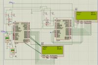
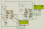
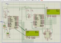
I am doing a project in which one PIC18f452 is connected to sensors, while second is with LCD i want to send data to from one PIC18f452 to other.
I am using full-duplex mode. Attached is the image of the working circuit.

I want to know that how long I'll able to send this data?
In other words what could be the maximum length of the cable between two PIC18f452?

Capture.PNG
 

hello,

add some details as :
how long is the distance between the 2 PIC ?
What is the UART speed ?
quality of cable ?
 

hello,

add some details as :
how long is the distance between the 2 PIC ?
What is the UART speed ?
quality of cable ?

Hi..
At-least 20 meters.
baud rate = 9600.
2-Wire.

- - - Updated - - -

If i put Max232 in the circuit the values on the same same code are not right.


hello
2-Wire. ? + 0V => 3 wires

you must use 2 max232 !
with RS232 level on PIC input you can destroy it !

PIC1 TTL level <->--///--- Max232 <-///-- RS232 levels --///- 20 meters---///---- Max232 --///-- <-> TTL level PIC2
 

Make it wireless bu using 2 XBees. You don't need MAX232 if you use XBees. You can also try I2C and wireless communication using nRF24L01+.
 

thanks paulfjujo

I only used 2 MAX232 and the result is fine...

I am fresh in embedded systems but this looks ok to me what do you say?

I only need PIC1 talking to PIC2 (it should be TTL level for that)


If no noisy environment, you can try direct connection TTL level
put a pull up resistor of 1Kohms on receiver side .

better could be to insert some buffer in the path
like trigger buffer 74HC14 ( 2 in serial to don't reverse the level).

What about galvanic insulation ?
is there a risk of diffrence of potential between the 0V of each module ?
 

Status
Not open for further replies.

Similar threads

Part and Inventory Search

Welcome to EDABoard.com

Sponsor

Back
Top